Quick Install Guide | 5 |
5.Install uplink modules (optional)
If you purchased uplink modules, install them now by following the instructions in the Uplink Module Quick Install Guide.
6.Place the switch in its operating location
If installing the switch in a rack:
•Remove the rubber feet.
•Attach the
•Mount the switch in the rack.
7.Check the supply voltage and the switch’s rated voltage
AC versions of
DC versions of
The specific power supply requirements for a particular model are clearly displayed on the rear or underside of the switch. If the supply is outside the accepted range for the switch, the switch may not operate or damage to the switch may result.
8.Apply AC power to the switch (for AC models)
Plug the power cord into the AC power connector on the switch’s rear panel. The Fault LED should flash for approximately 10 seconds as the switch runs internal tests. If the LED continues to flash or remains lit, refer to the
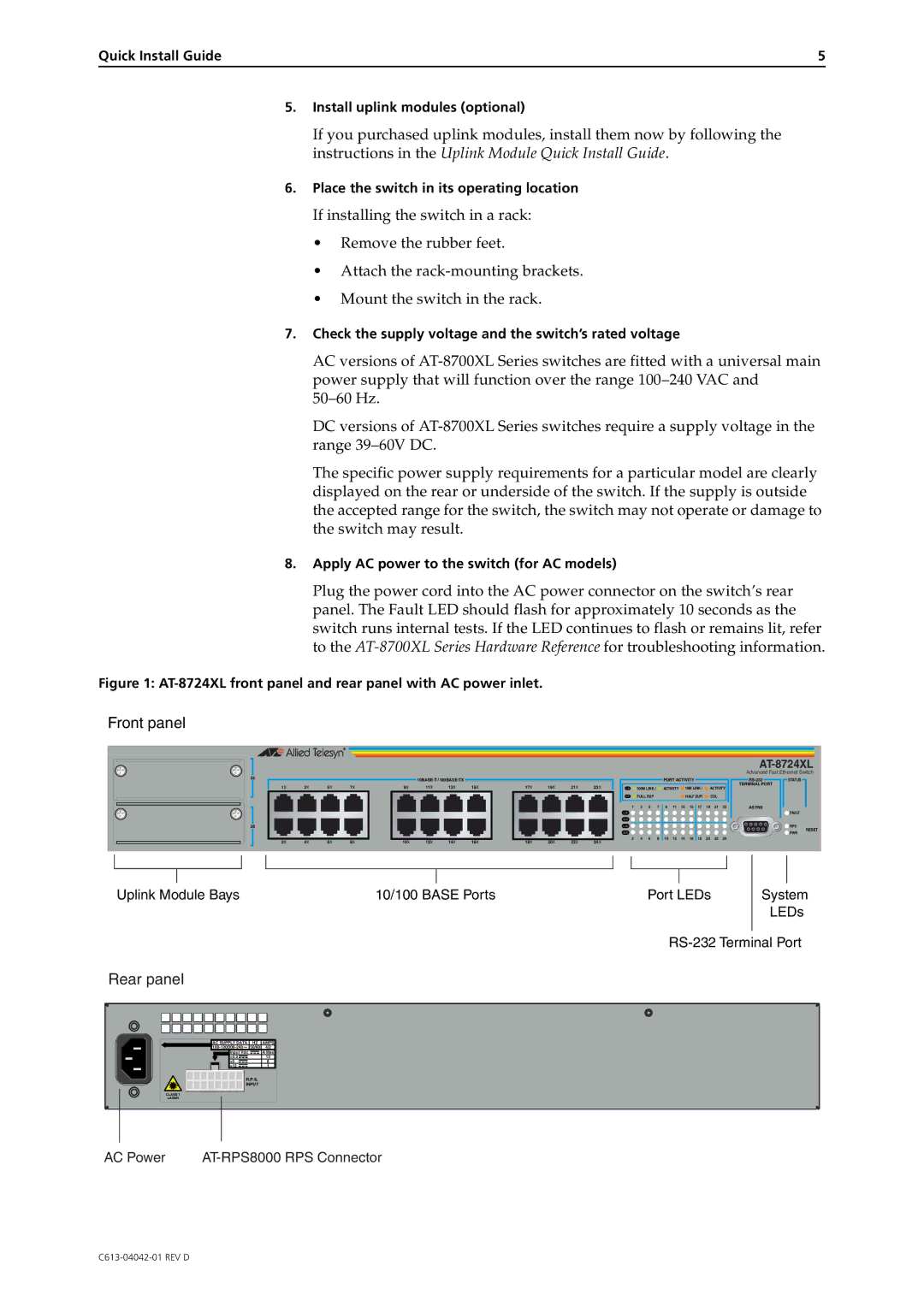
Figure 1: AT-8724XL front panel and rear panel with AC power inlet.
Front panel
|
|
|
|
|
|
|
|
|
|
|
|
|
|
|
|
|
|
|
|
|
|
|
|
| |
|
|
|
|
|
|
|
|
|
|
|
|
|
|
|
|
|
|
|
|
|
|
|
| Advanced Fast Ethernet Switch | |
25 |
|
|
|
|
|
|
|
|
|
|
|
|
| PORT ACTIVITY |
|
|
|
| STATUS | ||||||
1X | 3X | 5X | 7X | 9X | 11X | 13X | 15X | 17X | 19X | 21X | 23X |
| 100M LINK / |
| ACTIVITY |
| 10M LINK / |
| ACTIVITY | TERMINAL PORT |
| ||||
L /A |
|
|
|
|
| ||||||||||||||||||||
|
|
|
|
|
|
|
|
|
|
|
| D/C | FULL DUP |
|
|
|
| HALF DUP/ |
| COL |
|
|
| ||
|
|
|
|
|
|
|
|
|
|
|
| 1 | 3 | 5 | 7 | 9 | 11 | 13 | 15 | 17 | 19 | 21 | 23 | ASYN0 |
|
|
|
|
|
|
|
|
|
|
|
|
| L /A |
|
|
|
|
|
|
|
|
|
|
|
| FAULT |
|
|
|
|
|
|
|
|
|
|
|
| D/C |
|
|
|
|
|
|
|
|
|
|
|
|
|
26 |
|
|
|
|
|
|
|
|
|
|
| L /A |
|
|
|
|
|
|
|
|
|
|
|
| RPS |
|
|
|
|
|
|
|
|
|
|
|
| D/C |
|
|
|
|
|
|
|
|
|
|
|
| RESET |
|
|
|
|
|
|
|
|
|
|
|
|
|
|
|
|
|
|
|
|
|
|
|
| PWR | |
2X | 4X | 6X | 8X | 10X | 12X | 14X | 16X | 18X | 20X | 22X | 24X | 2 | 4 | 6 | 8 | 10 | 12 | 14 | 16 | 18 | 20 | 22 | 24 |
|
|
|
|
|
|
|
|
|
|
|
|
|
|
|
| ||||||||||||
Uplink Module Bays | 10/100 BASE Ports | Port LEDs |
System
LEDs
Rear panel
AC SUPPLY DATA | HZ | AMPS |
50/60 | 4/2 | |
Input Vdc |
| A Max |
+3.3 |
| 13 |
+5 |
| 8 |
+12 |
| 1 |
R.P.S.
INPUT
CLASS 1
LASER
AC Power |