Ethernet Cable Installation
AT-6101 PoE Injector Installation Guide
2.Install the two wall anchors into the wall at the locations marked in the previous step. The anchors require 0.635 mm (0.25 in.) holes.
3.Hold the power injector on the wall so that the mounting holes align with the anchors previously installed. Secure the unit with the two wall mounting screws as shown in Figure 6.
Figure 6. Securing the AT-6101GP PoE Injector to the Wall
4. Go to ”Ethernet Cable Installation” for the next step in the installation.
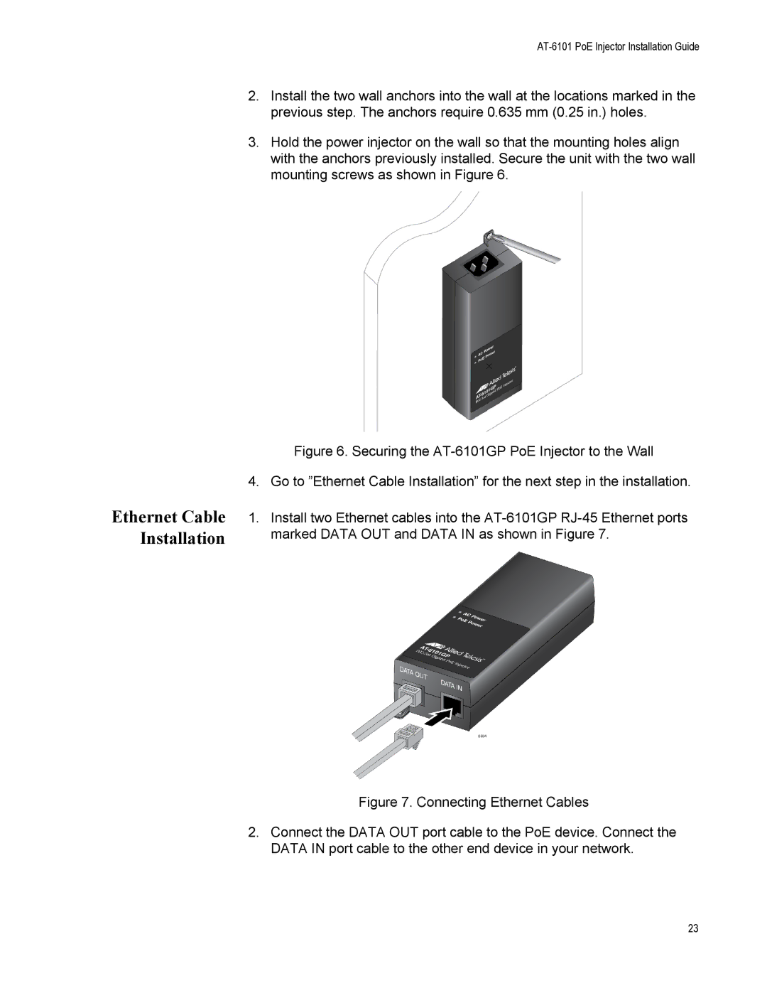
1.Install two Ethernet cables into the AT-6101GP RJ-45 Ethernet ports marked DATA OUT and DATA IN as shown in Figure 7.
Figure 7. Connecting Ethernet Cables
2.Connect the DATA OUT port cable to the PoE device. Connect the DATA IN port cable to the other end device in your network.
23