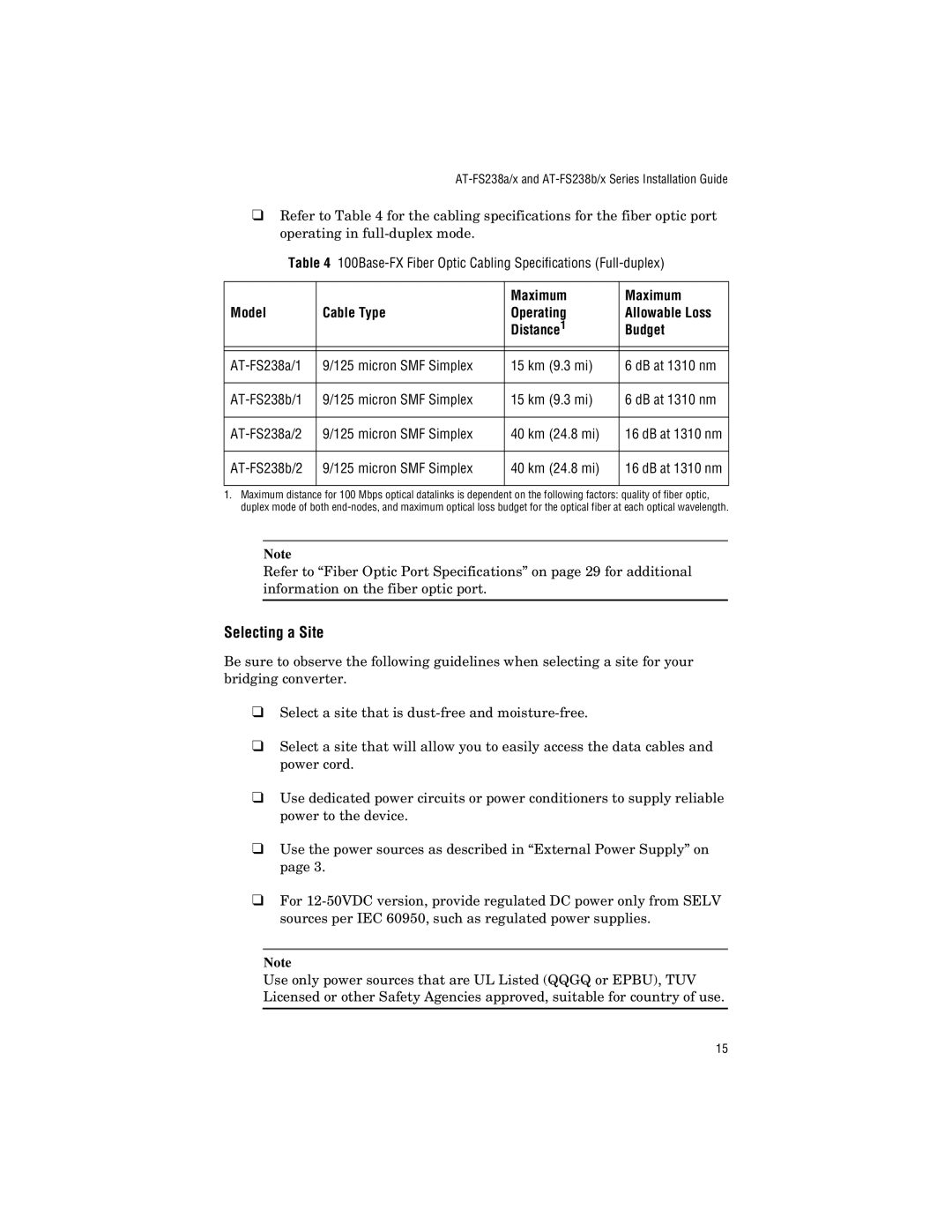
AT-FS238a/1, AT-FS238a/2, AT-FS238b/1, AT-FS238b/2 specifications
Allied Telesis is a renowned manufacturer specializing in networking solutions, and its AT-FS238 series of switches exemplifies the company's commitment to delivering high-quality networking hardware. The AT-FS238b/2, AT-FS238b/1, AT-FS238a/2, and AT-FS238a/1 are robust, cost-effective Ethernet switches that cater to various networking needs, including small to medium-sized enterprises and branch offices.These switches are designed with several key features that enhance performance and reliability. One of the standout characteristics is their support for high-speed connections, with 10/100/1000 Mbps ports that ensure fast data transfer rates and efficient network operations. This high-speed capability is essential for organizations that rely on bandwidth-intensive applications.
Allied Telesis AT-FS238 series switches incorporate advanced technology such as Auto-MDI/MDIX, which automatically detects the type of Ethernet cable connected and adjusts accordingly, eliminating the need for crossover cables. This feature significantly simplifies installation and reduces the likelihood of connectivity issues.
The switches also boast a metal chassis that offers durability and helps maintain optimal performance in various environments. With a robust design, these devices can withstand typical operational stresses, making them suitable for deployment in both office and industrial settings.
In terms of manageability, the AT-FS238 series provides basic configuration options through a user-friendly interface, making it accessible for IT staff who may not have extensive networking experience. The switches support plug-and-play functionality, allowing for seamless integration into existing networks without the need for extensive setup.
Power efficiency is another significant aspect of these switches, as they utilize energy-saving technologies that reduce operating costs while maintaining high performance. This characteristic aligns with the growing emphasis on sustainable tech solutions in modern networking.
Each model in the AT-FS238 series is equipped with a varying number of ports, catering to the specific needs of different networking scenarios. These options ensure that organizations can choose the right model that fits their scalability requirements.
In summary, the Allied Telesis AT-FS238b/2, AT-FS238b/1, AT-FS238a/2, and AT-FS238a/1 switches represent a solid choice for businesses seeking reliable and efficient networking solutions. Their combination of high-speed capabilities, user-friendly features, durable design, and energy efficiency makes them a valuable addition to any network infrastructure.

