AT-GS900/8PS Switch Installation Guide
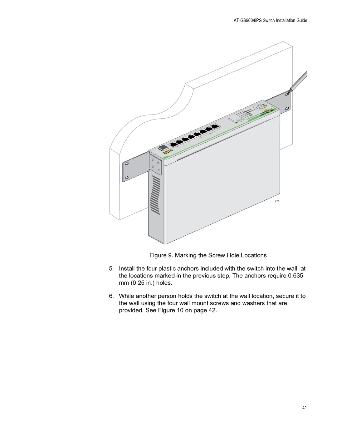
Figure 9. Marking the Screw Hole Locations
5.Install the four plastic anchors included with the switch into the wall, at the locations marked in the previous step. The anchors require 0.635 mm (0.25 in.) holes.
6.While another person holds the switch at the wall location, secure it to the wall using the four wall mount screws and washers that are provided. See Figure 10 on page 42.
41