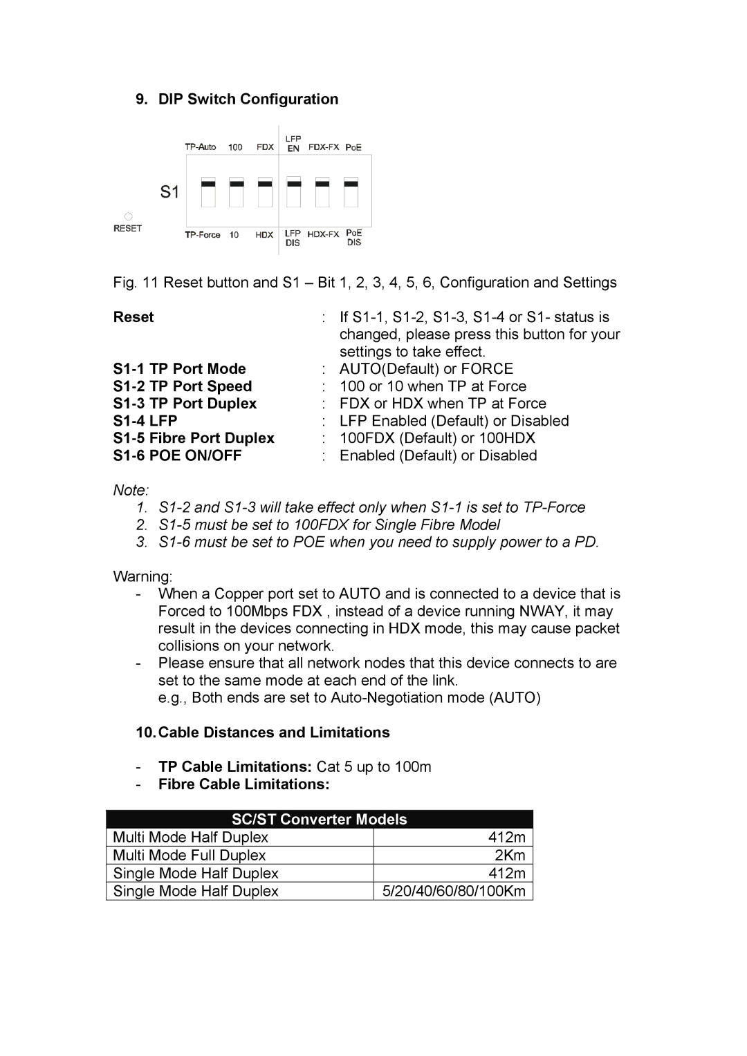
9. DIP Switch Configuration
Fig. 11 Reset button and S1 – Bit 1, 2, 3, 4, 5, 6, Configuration and Settings
Reset | : If | ||
|
|
| changed, please press this button for your |
|
|
| settings to take effect. |
: | AUTO(Default) or FORCE | ||
TP Port Speed | : 100 or 10 when TP at Force | ||
TP Port Duplex | : FDX or HDX when TP at Force | ||
: LFP Enabled (Default) or Disabled | |||
Fibre Port Duplex | : 100FDX (Default) or 100HDX | ||
| : | Enabled (Default) or Disabled | |
Note:
1.
2.
3.
Warning:
-When a Copper port set to AUTO and is connected to a device that is Forced to 100Mbps FDX , instead of a device running NWAY, it may result in the devices connecting in HDX mode, this may cause packet collisions on your network.
-Please ensure that all network nodes that this device connects to are set to the same mode at each end of the link.
e.g., Both ends are set to
10.Cable Distances and Limitations
-TP Cable Limitations: Cat 5 up to 100m
-Fibre Cable Limitations:
SC/ST Converter Models
Multi Mode Half Duplex | 412m |
Multi Mode Full Duplex | 2Km |
Single Mode Half Duplex | 412m |
Single Mode Half Duplex | 5/20/40/60/80/100Km |