Connections with other equipments
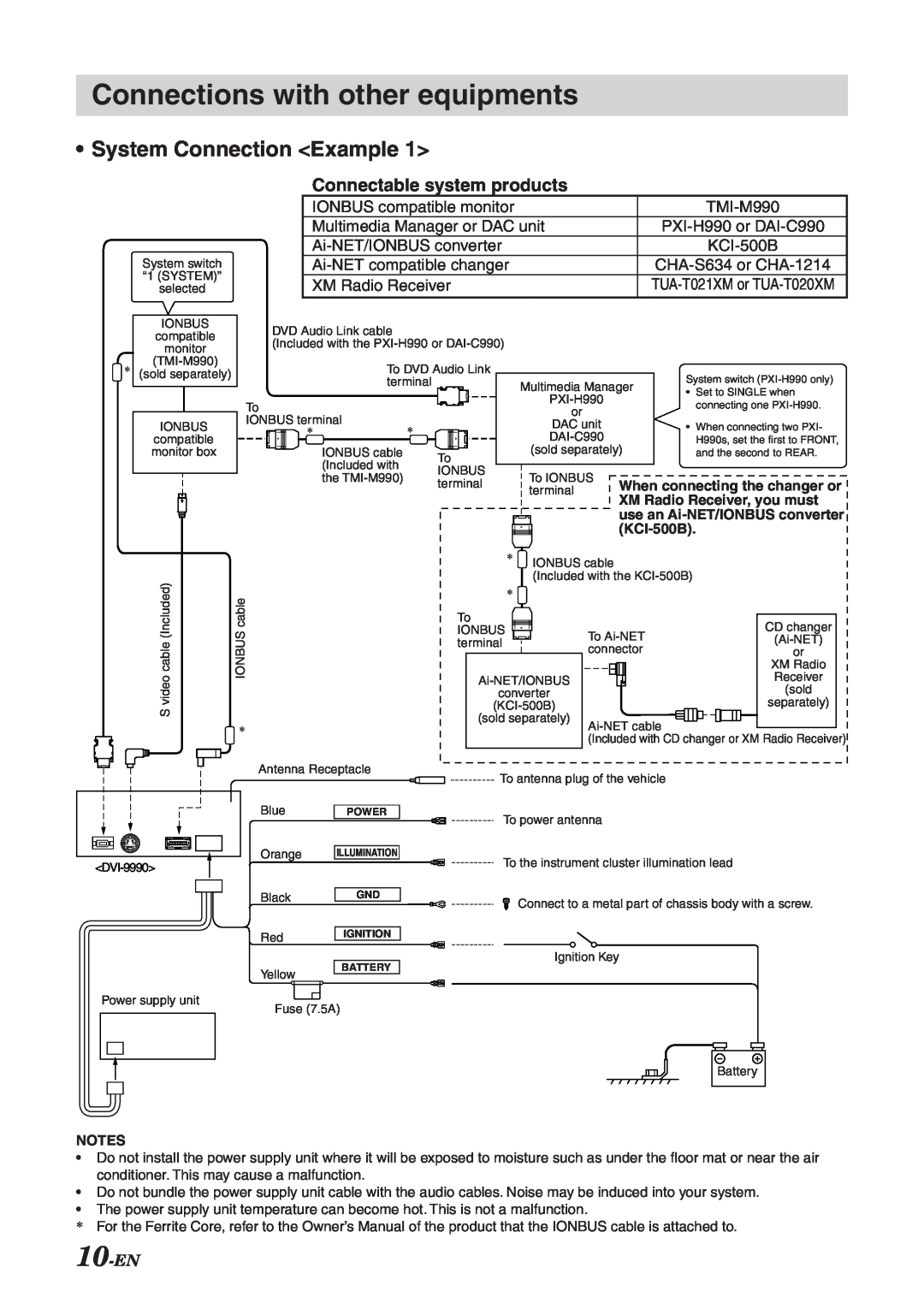
•System Connection <Example 1>
System switch “1 (SYSTEM)” selected
Connectable system products
IONBUS compatible monitor |
|
Multimedia Manager or DAC unit |
|
| |
| |
XM Radio Receiver |
*
IONBUS
compatible
monitor
(sold separately)
IONBUS
compatible monitor box
DVD Audio Link cable
(Included with the
|
|
|
|
|
|
|
| To DVD Audio Link |
|
|
|
|
| System switch | ||||||
|
|
|
|
|
|
|
| terminal |
| Multimedia Manager | ||||||||||
|
|
|
|
|
|
|
|
|
|
|
|
|
|
| • | Set to SINGLE when | ||||
|
|
|
|
|
|
|
|
|
|
|
|
|
|
|
|
|
| |||
To |
|
|
|
|
|
|
|
|
|
| connecting one | |||||||||
|
|
|
|
|
|
|
| or |
|
| ||||||||||
IONBUS terminal |
|
|
|
|
|
|
|
|
|
|
| |||||||||
* |
|
|
|
|
|
|
| DAC unit |
| • | When connecting two PXI- | |||||||||
|
|
|
|
|
|
|
| * |
|
|
|
|
|
|
|
| ||||
|
|
|
|
|
|
|
|
|
|
|
|
|
|
|
|
|
|
| H990s, set the first to FRONT, | |
|
|
|
|
|
|
|
| IONBUS cable |
|
|
|
|
|
|
|
| (sold separately) |
| and the second to REAR. | |
|
| To |
| |||||||||||||||||
|
|
|
|
|
|
|
| (Included with |
|
|
|
|
|
|
|
| ||||
|
|
|
|
|
|
|
|
| IONBUS |
|
|
|
|
|
|
| ||||
|
|
|
|
|
|
|
| the |
|
|
|
| To IONBUS |
|
|
| ||||
|
|
|
|
|
|
|
|
| terminal |
|
|
| When connecting the changer or | |||||||
|
|
|
|
|
|
|
|
|
|
|
|
| terminal | |||||||
|
|
|
|
|
|
|
|
|
|
|
|
|
|
|
|
| ||||
|
|
|
|
|
|
|
|
|
|
|
|
|
|
|
|
|
| XM Radio Receiver, you must | ||
|
|
|
|
|
|
|
|
|
|
|
|
|
|
|
|
|
| use an | ||
|
|
|
|
|
|
|
|
|
|
|
|
|
|
|
|
|
|
| ||
|
|
|
|
|
|
|
|
|
|
|
|
|
|
|
|
|
|
|
|
|
videocable(Included) |
|
|
| IONBUScable |
S |
|
|
|
|
| * | |||
|
|
|
|
|
|
|
|
|
|
|
|
|
|
|
* IONBUS cable
(Included with the
*
| To |
|
|
|
|
|
|
| CD changer |
| |||
| IONBUS |
|
|
|
|
|
|
| To |
| |||
| terminal |
|
|
|
|
|
|
|
| ||||
|
|
|
|
|
|
|
|
|
| connector | or |
| |
|
|
|
|
|
|
|
|
|
|
|
| XM Radio |
|
|
|
|
| Receiver |
| ||||||||
|
|
|
| (sold |
| ||||||||
|
| converter |
|
|
| ||||||||
|
|
|
| separately) |
| ||||||||
|
| (sold separately) |
|
|
|
| |||||||
|
|
|
| ||||||||||
|
|
|
|
|
|
|
|
|
|
|
| ||
|
|
|
|
|
|
|
|
|
| (Included with CD changer or XM Radio Receiver) | |||
Antenna Receptacle |
|
|
|
| |||||||||
|
| To antenna plug of the vehicle |
|
| |||||||||
|
|
|
|
BluePOWER
Orange ILLUMINATION
BlackGND
RedIGNITION
To power antenna
To the instrument cluster illumination lead
Connect to a metal part of chassis body with a screw.
Ignition Key
Yellow
BATTERY
Power supply unit
Fuse (7.5A)
Battery
NOTES
•Do not install the power supply unit where it will be exposed to moisture such as under the floor mat or near the air conditioner. This may cause a malfunction.
•Do not bundle the power supply unit cable with the audio cables. Noise may be induced into your system.
•The power supply unit temperature can become hot. This is not a malfunction.
*For the Ferrite Core, refer to the Owner’s Manual of the product that the IONBUS cable is attached to.