SWITCHERS
In addition to forward connection, the MX2214RM can be hooked up in reverse direction. In this configuration one video source is selectively sent to each of the video monitors. This capability is referred to as
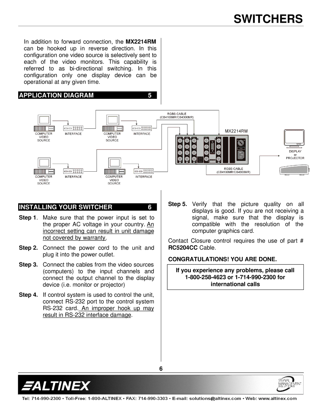
| APPLICATION DIAGRAM | 5 |
|
|
|
|
|
|
|
|
|
INSTALLING YOUR SWITCHER | 6 |
Step 1. Make sure that the power input is set to the proper AC voltage in your country. An incorrect setting can result in unit damage not covered by warranty.
Step 2. Connect the power cord to the unit and plug it into the power outlet.
Step 3. Connect the cables from the video sources (computers) to the input channels and connect the output channel to the display device (i.e. monitor or projector)
Step 4. If control system is used to control the unit, connect
Step 5. Verify that the picture quality on all displays is good. If you are not receiving a signal, make sure that the display is compatible with the resolution of the computer graphics card.
Contact Closure control requires the use of part # RC5204CC Cable.
CONGRATULATIONS! YOU ARE DONE.
If you experience any problems, please call
international calls
6