SWITCHERS
OPERATION | 7 |
7.1 RS-232 CONTROL
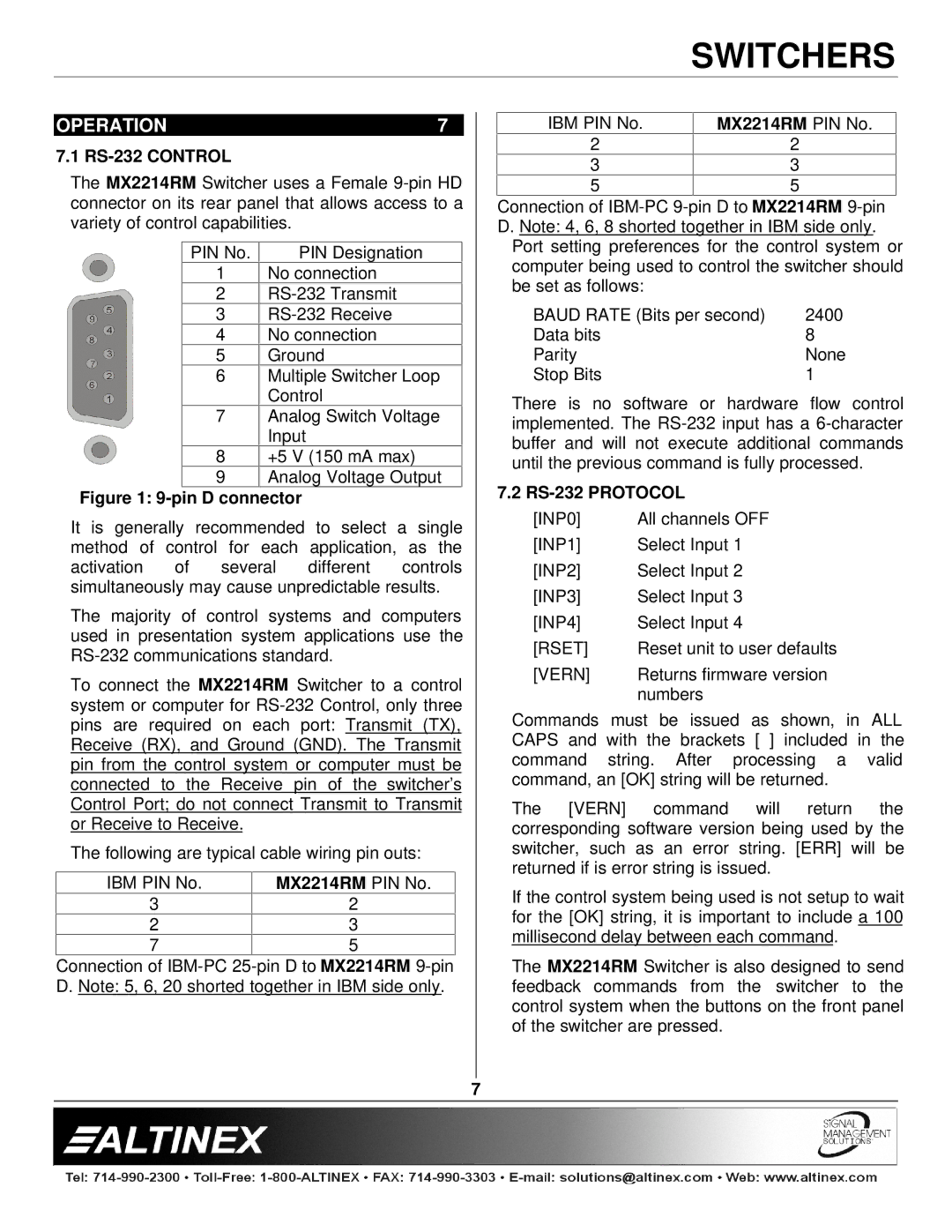
The MX2214RM Switcher uses a Female
PIN No. | PIN Designation |
1No connection
2
3
4No connection
5Ground
6Multiple Switcher Loop Control
7Analog Switch Voltage Input
8+5 V (150 mA max)
9Analog Voltage Output
Figure 1: 9-pin D connector
It is generally recommended to select a single method of control for each application, as the activation of several different controls simultaneously may cause unpredictable results.
The majority of control systems and computers used in presentation system applications use the
To connect the MX2214RM Switcher to a control system or computer for
The following are typical cable wiring pin outs:
IBM PIN No. | MX2214RM PIN No. |
3 | 2 |
2 | 3 |
7 | 5 |
Connection of
IBM PIN No. | MX2214RM PIN No. |
2 | 2 |
3 | 3 |
5 | 5 |
Connection of
Port setting preferences for the control system or computer being used to control the switcher should be set as follows:
BAUD RATE (Bits per second) | 2400 |
Data bits | 8 |
Parity | None |
Stop Bits | 1 |
There is no software or hardware flow control implemented. The
7.2 RS-232 PROTOCOL
[INP0] | All channels OFF |
[INP1] | Select Input 1 |
[INP2] | Select Input 2 |
[INP3] | Select Input 3 |
[INP4] | Select Input 4 |
[RSET] | Reset unit to user defaults |
[VERN] | Returns firmware version |
| numbers |
Commands must be issued as shown, in ALL CAPS and with the brackets [ ] included in the command string. After processing a valid command, an [OK] string will be returned.
The [VERN] command will return the corresponding software version being used by the switcher, such as an error string. [ERR] will be returned if is error string is issued.
If the control system being used is not setup to wait for the [OK] string, it is important to include a 100 millisecond delay between each command.
The MX2214RM Switcher is also designed to send feedback commands from the switcher to the control system when the buttons on the front panel of the switcher are pressed.
7