DESIGNER SOLUTIONS
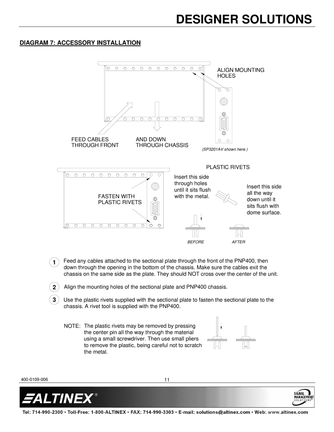
DIAGRAM 7: ACCESSORY INSTALLATION
ALIGN MOUNTING
HOLES
FEED CABLES | AND DOWN |
THROUGH FRONT | THROUGH CHASSIS |
(SP3201AV shown here.)
| PLASTIC RIVETS | ||
| Insert this side |
| |
| through holes | Insert this side | |
| until it sits flush | ||
| all the way | ||
FASTEN WITH | with the metal. | ||
down until it | |||
PLASTIC RIVETS |
| ||
| sits flush with | ||
|
| ||
|
| dome surface. | |
| BEFORE | AFTER | |
1Feed any cables attached to the sectional plate through the front of the PNP400, then down through the opening in the bottom of the chassis. Make sure the cables exit the chassis on the same side as the plate. They should NOT cross over the center of the unit.
2
3
Align the mounting holes of the sectional plate and PNP400 chassis.
Use the plastic rivets supplied with the sectional plate to fasten the sectional plate to the chassis. A rivet tool is supplied with the PNP400.
NOTE: The plastic rivets may be removed by pressing the center pin all the way through the material using a small screwdriver. Then use small pliers to remove the plastic, being careful not to scratch the metal.
11 |