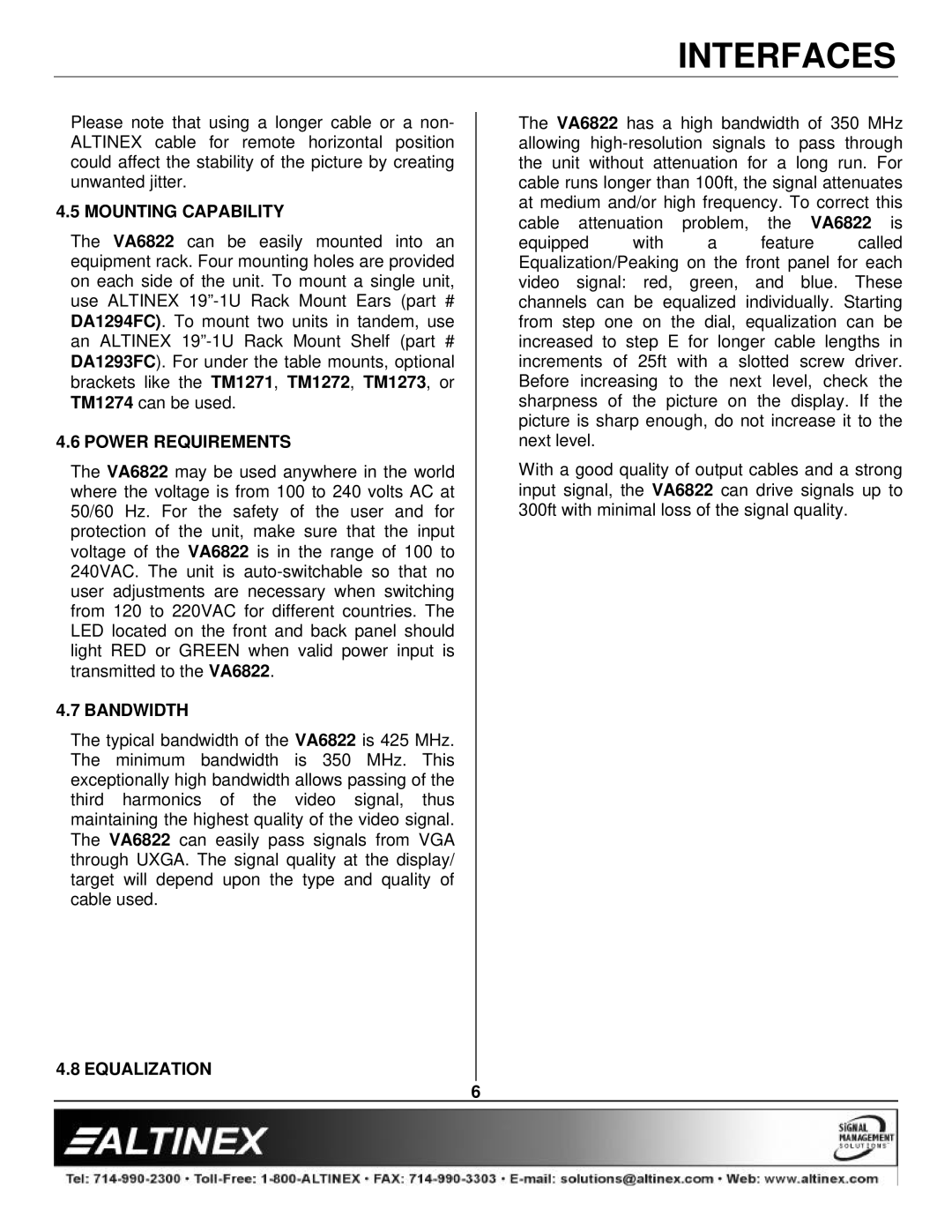
VA6822 specifications
The Altinex VA6822 is a versatile and innovative solution designed to meet the evolving needs of modern presentation environments. As a part of Altinex's diverse range of AV products, the VA6822 is specifically engineered to facilitate seamless integration of various audio-visual devices, making it an ideal choice for conference rooms, classrooms, and other collaborative spaces.One of the primary features of the VA6822 is its ability to support multiple video formats, including HDMI, DisplayPort, and VGA. This flexibility allows users to connect various devices from laptops to projectors, ensuring compatibility with a wide array of equipment. Enhanced with automatic input detection, the VA6822 intelligently identifies the connected source, providing users with a hassle-free experience without the need for manual adjustments.
The VA6822 also boasts a compact and elegant design, which can easily blend into any environment without being obtrusive. Its robust construction ensures durability while maintaining a lightweight profile, making it easy to install in both new and existing setups. The device is engineered for efficiency, with low power consumption that meets the demands of eco-conscious users.
An important technological highlight of the VA6822 is its advanced video scaling capabilities. With the ability to output high-resolution video at up to 4K, users can experience crystal-clear images and sharp graphics. This feature is particularly beneficial in professional settings, where detail is crucial for effective communication and presentations.
In addition to its video capabilities, the VA6822 includes audio routing features that enhance sound clarity. It supports both analog and digital audio formats, allowing for a seamless audio experience across different devices. When paired with compatible audio systems, users will appreciate the high-quality sound that this unit can deliver.
Furthermore, the VA6822 offers intuitive control options. Users have the ability to manage the device through various methods, including front panel buttons, remote control, or even control via RS-232 for integration with third-party control systems. This level of control simplifies operation, making it accessible for users of all technical skill levels.
In summary, the Altinex VA6822 is an advanced AV solution featuring multiple input formats, superb video scaling capabilities, and versatile audio routing options. Its user-friendly design and flexible integration make it an invaluable asset for any presentation environment, helping to enhance collaboration and communication in today’s fast-paced world.

