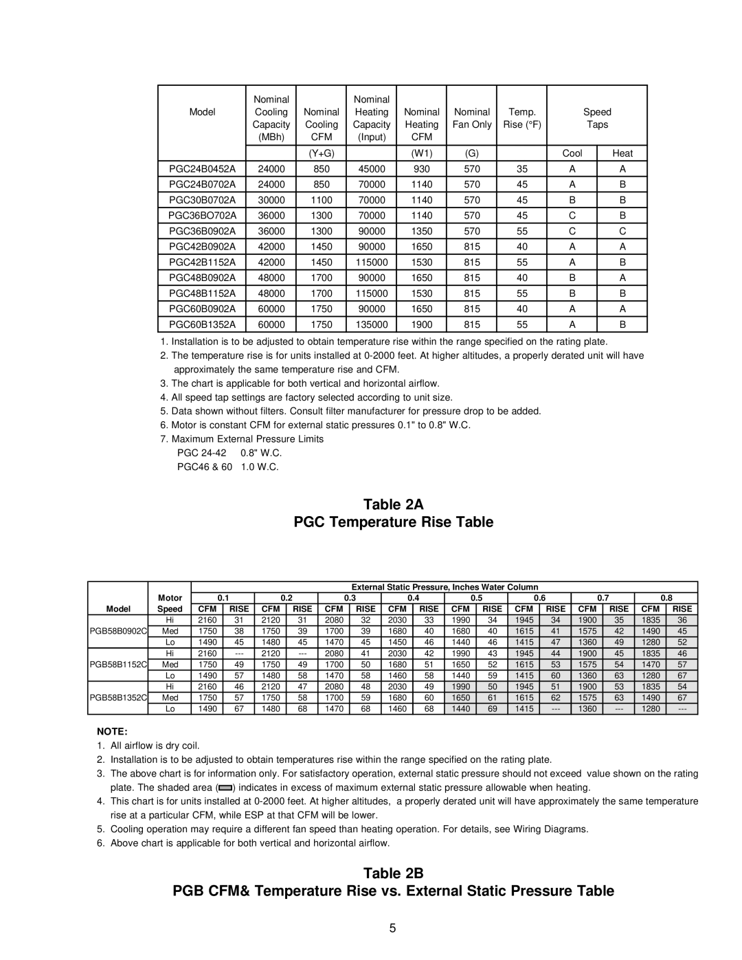
PGB58B, PGC(24-60)B specifications
Amana, a trusted name in heating and cooling, offers several high-efficiency gas furnace models, including the PGC(24-60)B and PGB58B. These furnaces combine innovation, reliability, and advanced technology to provide an optimal heating solution for any home.One of the standout features of the Amana PGC(24-60)B is its modulating heating capability. This technology allows the furnace to operate at different heating levels based on the home’s demands. Instead of simply turning on and off, the PGC adjusts its output to maintain a consistent temperature, promoting energy efficiency and comfort. This not only reduces energy consumption but also minimizes temperature fluctuations, providing a more comfortable indoor environment.
The PGB58B model is designed with a focus on efficiency, boasting an Annual Fuel Utilization Efficiency (AFUE) rating of up to 96%. This means that a higher percentage of the fuel used is converted into heat, making it one of the most efficient choices available. The combination of high-efficiency design and advanced components makes the PGB58B an excellent option for homeowners looking to reduce their energy bills while enjoying reliable heating performance.
Both models come equipped with a durable casing, ensuring longevity and performance. The rust-resistant and heavy-gauge steel construction protects against harsh weather conditions, making them suitable for various climates. Additionally, they feature a multi-speed blower motor, which optimizes airflow and enhances comfort by evenly distributing warm air throughout the home.
Advanced diagnostics and self-monitoring capabilities are integral to these models. The built-in diagnostic system enables quick identification of performance issues, allowing for timely maintenance and reducing repair costs. Furthermore, these furnaces are designed to be compatible with smart home technology, allowing homeowners to control their heating systems remotely and maximize energy efficiency.
In summary, the Amana PGC(24-60)B and PGB58B gas furnaces stand out for their innovative features and commitment to energy efficiency. With modulating heating, high AFUE ratings, durable construction, and smart technology compatibility, they offer reliable heating solutions that ensure comfort while keeping energy costs low. Homeowners can feel confident in their investment, knowing they have chosen a furnace that prioritizes both performance and sustainability.
