Initialization | 32430C |
|
|
Initialization4
4.1Processor Initialization
The AMD Geode™ GX processor contains many of the components normally found in system support chipsets. GeodeROM must set up these components, including the DRAM controller, L1 cache controller, clock control, and PCI con- troller as well as some proprietary systems like GeodeLink™ architecture.
This chapter contains descriptions and some pseudo code for GX
4.1.1Set Clocks and Reset
Register: GLCP_SYS_RSTPLL (GX GLCP MSR Address 4C000014h)
The GX processor has separate clocks for the CPU core and GeodeLink interface. These clocks are derived from the sys- tem PLL, which is driven by the PCI clock. At
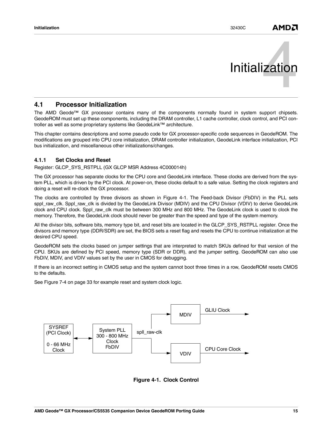
The clocks are controlled by three divisors as shown in Figure
All the divisor bits, software bits, memory type bit, and reset bits are located in the GLCP_SYS_RSTPLL register. Once the divisors and memory type (DDR/SDR) are set, the BIOS sets a reset flag and resets the CPU to continue initialization at the desired CPU speed.
GeodeROM sets the clocks based on jumper settings that are interpreted to match SKUs defined for that version of the CPU. SKUs are defined by PCI speed, memory type (SDR or DDR), and the jumper setting. GeodeROM can also use FbDIV, MDIV, and VDIV values set by the user in CMOS for debugging.
If there is an incorrect setting in CMOS setup and the system cannot boot three times in a row, GeodeROM resets CMOS to the defaults.
See Figure
GLIU Clock
SYSREF
(PCI Clock)
0 - 66 MHz
Clock
System PLL
300 - 800 MHz
Clock
FbDIV
MDIV
VDIV
CPU Core Clock
Figure 4-1. Clock Control
AMD Geode™ GX Processor/CS5535 Companion Device GeodeROM Porting Guide | 15 |