SCD-100 specifications
The American Audio SCD-100 is a state-of-the-art compact disc player designed for professional DJs and audio enthusiasts. This unit combines durability, functionality, and user-friendliness, making it an ideal choice for both live performances and studio use. With its robust construction and advanced features, the SCD-100 is engineered to withstand the rigors of the demanding DJ environment.One of the standout features of the SCD-100 is its seamless integration with various audio formats. While predominantly a CD player, it also supports playback of MP3 discs, providing users with the flexibility to access a vast library of music. This capability is particularly appealing for DJs who require a diverse range of tracks at their fingertips.
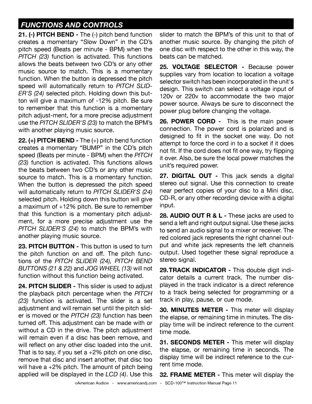
The SCD-100 is equipped with a high-quality digital-to-analog converter (DAC), which ensures pristine audio output with minimal distortion. This technology contributes to the clarity and depth of the sound, a crucial aspect for any professional application. The player also features a pitch control function, allowing DJs to adjust the tempo of their tracks without compromising the audio quality. This makes beat matching and transitions between songs smoother, resulting in an enhanced listening experience.
In terms of usability, the SCD-100 boasts an intuitive interface, featuring a large backlit LCD display that provides essential information at a glance. The buttons and jog wheels are well-placed, allowing for quick and precise navigation through folders and tracks. Additionally, the unit has a range of playback functions, including loop, cue, and reverse playback, which provide DJs with creative control over their sets.
Another significant characteristic of the American Audio SCD-100 is its versatility in connectivity. The player includes multiple output options, such as RCA and XLR connections, which allows users to connect to various sound systems effortlessly. Furthermore, the SCD-100 can be easily integrated into existing DJ setups, making it a valuable addition to any equipment collection.
In conclusion, the American Audio SCD-100 is a highly capable CD player that meets the demands of both professional and amateur DJs. Its combination of advanced technology, durable design, and user-friendly features ensures that it stands out in a crowded market. Whether for live performances or studio use, the SCD-100 promises to deliver high-quality sound and reliable performance every time.
