CE Hot Surface Ignition Burner Assembly
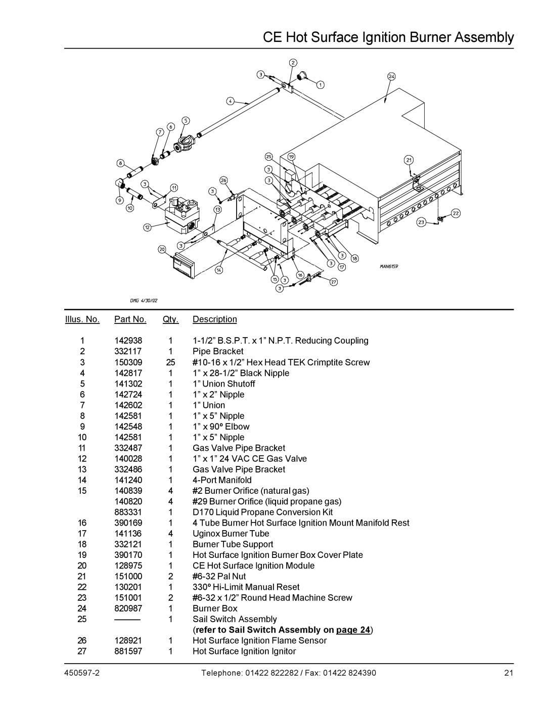
Illus. No. | Part No. | Qty. | Description |
1 | 142938 | 1 | |
2 | 332117 | 1 | Pipe Bracket |
3 | 150309 | 25 | |
4 | 142817 | 1 | 1” x |
5 | 141302 | 1 | 1” Union Shutoff |
6 | 142724 | 1 | 1” x 2” Nipple |
7 | 142602 | 1 | 1” Union |
8 | 142581 | 1 | 1” x 5” Nipple |
9 | 142548 | 1 | 1” x 90º Elbow |
10 | 142581 | 1 | 1” x 5” Nipple |
11 | 332487 | 1 | Gas Valve Pipe Bracket |
12 | 140028 | 1 | 1” x 1” 24 VAC CE Gas Valve |
13 | 332486 | 1 | Gas Valve Pipe Bracket |
14 | 141240 | 1 | |
15 | 140839 | 4 | #2 Burner Orifice (natural gas) |
| 140820 | 4 | #29 Burner Orifice (liquid propane gas) |
| 883331 | 1 | D170 Liquid Propane Conversion Kit |
16 | 390169 | 1 | 4 Tube Burner Hot Surface Ignition Mount Manifold Rest |
17 | 141136 | 4 | Uginox Burner Tube |
18 | 332121 | 1 | Burner Tube Support |
19 | 390170 | 1 | Hot Surface Ignition Burner Box Cover Plate |
20 | 128975 | 1 | CE Hot Surface Ignition Module |
21 | 151000 | 2 | |
22 | 130201 | 1 | 330º |
23 | 151001 | 2 | |
24 | 820987 | 1 | Burner Box |
25 | 1 | Sail Switch Assembly | |
|
|
| (refer to Sail Switch Assembly on page 24) |
26 | 128921 | 1 | Hot Surface Ignition Flame Sensor |
27 | 881597 | 1 | Hot Surface Ignition Ignitor |
Telephone: 01422 822282 / Fax: 01422 824390 | 21 |