Back Guard Assemblies
Illus. No. | Part No. | Qty. | Description |
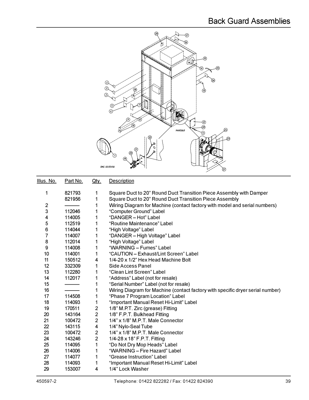
1 | 821793 | 1 | Square Duct to 20” Round Duct Transition Piece Assembly with Damper |
| 821956 | 1 | Square Duct to 20” Round Duct Transition Piece Assembly |
2 | 1 | Wiring Diagram for Machine (contact factory with model and serial numbers) | |
3 | 112046 | 1 | “Computer Ground” Label |
4 | 114005 | 1 | “DANGER – Hot” Label |
5 | 112519 | 1 | “Routine Maintenance” Label |
6 | 114044 | 1 | “High Voltage” Label |
7 | 114007 | 1 | “DANGER – High Voltage” Label |
8 | 112014 | 1 | “High Voltage” Label |
9 | 114008 | 1 | “WARNING – Fumes” Label |
10 | 114001 | 1 | “CAUTION – Exhaust/Lint Screen” Label |
11 | 150512 | 4 | |
12 | 332309 | 1 | Side Access Panel |
13 | 112280 | 1 | “Clean Lint Screen” Label |
14 | 112017 | 1 | “Address” Label (not for resale) |
15 | 1 | “Serial Number” Label (not for resale) | |
16 | 1 | Wiring Diagram for Machine (contact factory with specific dryer serial number) | |
17 | 114508 | 1 | “Phase 7 Program Location” Label |
18 | 114093 | 1 | “Important Manual Reset |
19 | 170511 | 2 | 1/8” M.P.T. Zirc (grease) Fitting |
20 | 143164 | 2 | 1/8” F.P.T. Bulkhead Fitting |
21 | 100472 | 2 | 1/4” x 1/8” M.P.T. Male Connector |
22 | 143115 | 4 | 1/4” |
23 | 100472 | 2 | 1/4” x 1/8” M.P.T. Male Connector |
24 | 143246 | 2 | |
25 | 114095 | 1 | “Do Not Dry Mop Heads” Label |
26 | 114006 | 1 | “WARNING – Fire Hazard” Label |
27 | 114077 | 1 | “Grease Instruction” Label |
28 | 114093 | 1 | “Important Manual Reset |
29 | 153007 | 4 | 1/4” Lock Washer |
Telephone: 01422 822282 / Fax: 01422 824390 | 39 |