Each dryer should be connected to an independently protected branch circuit. The dryer must be connected with copper wire only. DO NOT use aluminum wire, which could cause a fire hazard. The copper conductor wire or cable must be of proper ampacity and insulation in accordance with electric codes for making ALL service connections.
NOTE: The use of aluminum wire will VOID THE WARRANTY.
IMPORTANT: Wiring diagrams are affixed to the inside at the top front control door and to the rear upper back guard or panel.
2.Electrical Service Specifications
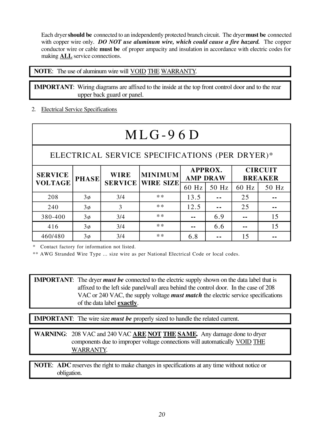
M L G - 9 6 D
ELECTRICAL SERVICE SPECIFICATIONS (PER DRYER)*
SERVICE |
| WIRE | MINIMUM | APPROX. | CIRCUIT | |||
PHASE | AMP DRAW | BREAKER | ||||||
VOLTAGE | SERVICE | WIRE SIZE | ||||||
60 Hz | 50 Hz | 60 Hz | 50 Hz | |||||
|
|
|
| |||||
2 0 8 | 3 ø | 3/4 | ** | 13 . 5 | 25 | |||
2 4 0 | 3 ø | 3 | ** | 12 . 5 | 25 | |||
3 8 0 - 4 0 0 | 3 ø | 3/4 | ** | 6 . 9 | 15 | |||
4 1 6 | 3 ø | 3/4 | ** | 6 . 6 | 15 | |||
|
|
|
|
|
|
|
| |
460/480 | 3 ø | 3/4 | ** | 6.8 | 15 | |||
*Contact factory for information not listed.
**AWG Stranded Wire Type ... size wire as per National Electrical Code or local codes.
IMPORTANT: The dryer must be connected to the electric supply shown on the data label that is affixed to the left side panel/wall area behind the control door. In the case of 208 VAC or 240 VAC, the supply voltage must match the electric service specifications of the data label exactly.
IMPORTANT: The wire size must be properly sized to handle the related current.
WARNING: 208 VAC and 240 VAC ARE NOT THE SAME. Any damage done to dryer components due to improper voltage connections will automatically VOID THE WARRANTY.
NOTE: ADC reserves the right to make changes in specifications at any time without notice or obligation.
20