American Dryer Corp MLG33 manual Fresh Air Supply Requirements, Exhaust Requirements

Models: MLG33

1 22
Download 22 pages 46.82 Kb
Page 9
Image 9

Fresh Air Supply Requirements _______

When the dryer is operating, it draws in room air, heats it, passes this air through the tumbler, and exhausts it out of the building. Therefore, the room air must be continually replenished from the outdoors. If the make-up air is inadequate, drying time and drying efficiency will be adversely affected. Ignition problems and sail switch “fluttering” problems may result, as well as premature motor failure from overheating. The dryer must be installed with provisions for adequate combustion and make-up air supply.

Air supply (make-up air) must be given careful consideration to ensure proper performance of each dryer. As a general rule, an unrestricted air entrance from the outdoors of 110 inch2 (710 cm2) is required for each dryer. (Based on 1 inch2 [6.5 cm2] per 1,000 Btu [252 kcal].)

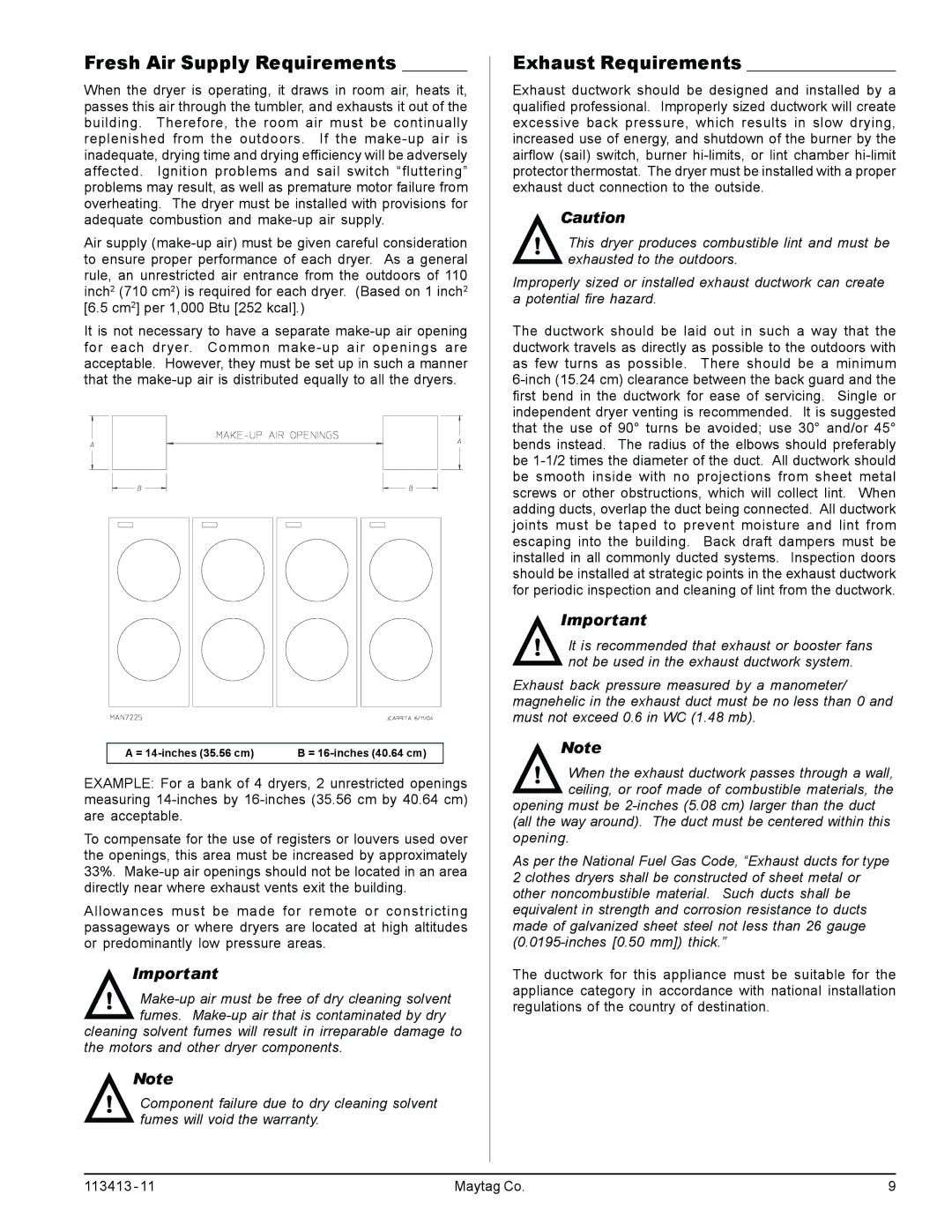
It is not necessary to have a separate make-up air opening for each dryer. Common make-up air openings are acceptable. However, they must be set up in such a manner that the make-up air is distributed equally to all the dryers.

A = 14-inches (35.56 cm)

B = 16-inches (40.64 cm)


EXAMPLE: For a bank of 4 dryers, 2 unrestricted openings measuring 14-inches by 16-inches (35.56 cm by 40.64 cm) are acceptable.

To compensate for the use of registers or louvers used over the openings, this area must be increased by approximately 33%. Make-up air openings should not be located in an area directly near where exhaust vents exit the building.

Allowances must be made for remote or constricting passageways or where dryers are located at high altitudes or predominantly low pressure areas.

Important

!Make-up air must be free of dry cleaning solvent fumes. Make-up air that is contaminated by dry

cleaning solvent fumes will result in irreparable damage to the motors and other dryer components.

Note

!Component failure due to dry cleaning solvent fumes will void the warranty.

Exhaust Requirements ________________

Exhaust ductwork should be designed and installed by a qualified professional. Improperly sized ductwork will create excessive back pressure, which results in slow drying, increased use of energy, and shutdown of the burner by the airflow (sail) switch, burner hi-limits, or lint chamber hi-limit protector thermostat. The dryer must be installed with a proper exhaust duct connection to the outside.

Caution

!This dryer produces combustible lint and must be exhausted to the outdoors.

Improperly sized or installed exhaust ductwork can create a potential fire hazard.

The ductwork should be laid out in such a way that the ductwork travels as directly as possible to the outdoors with as few turns as possible. There should be a minimum 6-inch (15.24 cm) clearance between the back guard and the first bend in the ductwork for ease of servicing. Single or independent dryer venting is recommended. It is suggested that the use of 90° turns be avoided; use 30° and/or 45° bends instead. The radius of the elbows should preferably be 1-1/2 times the diameter of the duct. All ductwork should be smooth inside with no projections from sheet metal screws or other obstructions, which will collect lint. When adding ducts, overlap the duct being connected. All ductwork joints must be taped to prevent moisture and lint from escaping into the building. Back draft dampers must be installed in all commonly ducted systems. Inspection doors should be installed at strategic points in the exhaust ductwork for periodic inspection and cleaning of lint from the ductwork.

Important

!It is recommended that exhaust or booster fans not be used in the exhaust ductwork system.

Exhaust back pressure measured by a manometer/ magnehelic in the exhaust duct must be no less than 0 and must not exceed 0.6 in WC (1.48 mb).

Note

!When the exhaust ductwork passes through a wall, ceiling, or roof made of combustible materials, the

opening must be 2-inches (5.08 cm) larger than the duct (all the way around). The duct must be centered within this opening.

As per the National Fuel Gas Code, “Exhaust ducts for type 2 clothes dryers shall be constructed of sheet metal or other noncombustible material. Such ducts shall be equivalent in strength and corrosion resistance to ducts made of galvanized sheet steel not less than 26 gauge (0.0195-inches [0.50 mm]) thick.”

The ductwork for this appliance must be suitable for the appliance category in accordance with national installation regulations of the country of destination.

113413 - 11

Maytag Co.

9

Page 9
Image 9
American Dryer Corp MLG33 manual Fresh Air Supply Requirements, Exhaust Requirements