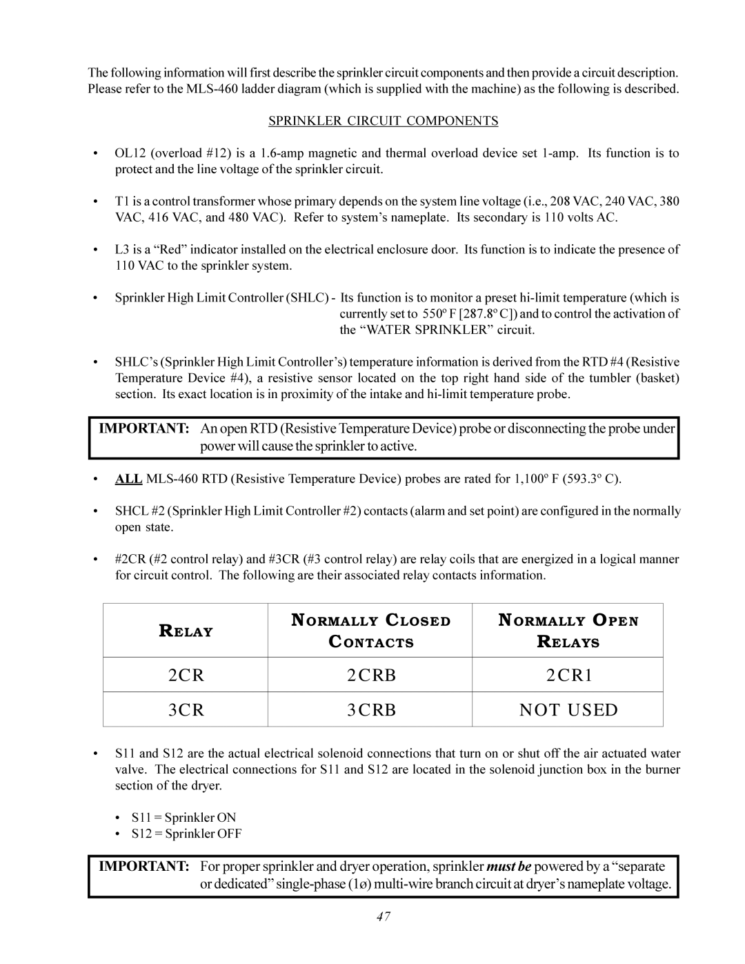
The following information will first describe the sprinkler circuit components and then provide a circuit description. Please refer to the
SPRINKLER CIRCUIT COMPONENTS
•OL12 (overload #12) is a
•T1 is a control transformer whose primary depends on the system line voltage (i.e., 208 VAC, 240 VAC, 380 VAC, 416 VAC, and 480 VAC). Refer to system’s nameplate. Its secondary is 110 volts AC.
•L3 is a “Red” indicator installed on the electrical enclosure door. Its function is to indicate the presence of 110 VAC to the sprinkler system.
•Sprinkler High Limit Controller (SHLC) - Its function is to monitor a preset
•SHLC’s (Sprinkler High Limit Controller’s) temperature information is derived from the RTD #4 (Resistive Temperature Device #4), a resistive sensor located on the top right hand side of the tumbler (basket) section. Its exact location is in proximity of the intake and
IMPORTANT: An open RTD (Resistive Temperature Device) probe or disconnecting the probe under power will cause the sprinkler to active.
•ALL
•SHCL #2 (Sprinkler High Limit Controller #2) contacts (alarm and set point) are configured in the normally open state.
•#2CR (#2 control relay) and #3CR (#3 control relay) are relay coils that are energized in a logical manner for circuit control. The following are their associated relay contacts information.
RELAY | NORMALLY CLOSED | NORMALLY OPEN | |
CONTACTS | RELAYS | ||
| |||
|
|
| |
2C R | 2 C RB | 2 C R1 | |
|
|
| |
3CR | 3 CRB | NOT USED | |
|
|
|
•S11 and S12 are the actual electrical solenoid connections that turn on or shut off the air actuated water valve. The electrical connections for S11 and S12 are located in the solenoid junction box in the burner section of the dryer.
•S11 = Sprinkler ON
•S12 = Sprinkler OFF
IMPORTANT: For proper sprinkler and dryer operation, sprinkler must be powered by a “separate or dedicated”
47
