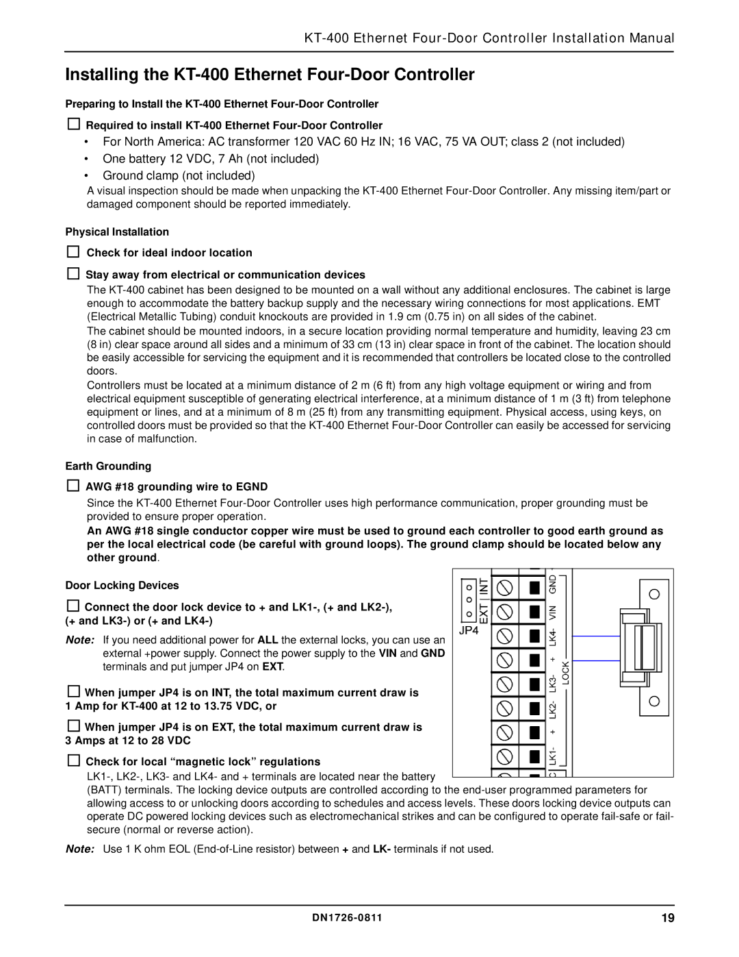
KT-400 specifications
The American Dynamics KT-400 is a robust and versatile video management system designed for a wide range of security applications. As a part of American Dynamics' extensive lineup of surveillance solutions, the KT-400 caters to various industries, including retail, transportation, and critical infrastructure, enabling efficient surveillance and management of video data.One of the main features of the KT-400 is its exceptional scalability. The system can support a large number of cameras, making it suitable for both small and expansive enterprises. Users can easily manage thousands of video feeds, enabling effective monitoring of large facilities or multiple locations from a centralized interface. This scalability is complemented by its user-friendly web-based interface, which allows operators to access the system remotely, providing flexibility and convenience.
In terms of technology, the KT-400 employs advanced video analytics capabilities. These analytics enhance security measures by allowing the system to detect unusual activities, such as unauthorized access or suspicious behavior, reducing reliance on manual monitoring. The analytics can send instant alerts, which can significantly improve response time during security incidents. Integration with other security systems, such as access control and intrusion detection systems, further enhances its effectiveness.
The KT-400 is designed for high-performance video recording, featuring high-resolution recording capabilities that ensure clear and detailed footage, crucial for identification purposes. The system also supports various compression standards, optimizing storage use while maintaining video quality. Coupled with its redundancy features, such as failover capabilities, the KT-400 ensures that critical video data is preserved even in the event of hardware failures.
Moreover, the KT-400 supports a wide range of camera types, including IP and analog cameras, making it a versatile choice for existing legacy systems as well as new installations. This compatibility, along with support for various video formats, allows for seamless integration, providing users with the flexibility to design their surveillance systems according to their needs.
In conclusion, the American Dynamics KT-400 stands out for its scalability, advanced video analytics, high-performance recording, and broad compatibility with different camera types. These features make it an ideal choice for organizations looking to enhance their security management and respond swiftly to potential threats. With ongoing technological advancements, the KT-400 is poised to remain a reliable choice in the evolving security landscape.

