3. Connect the External Batteries
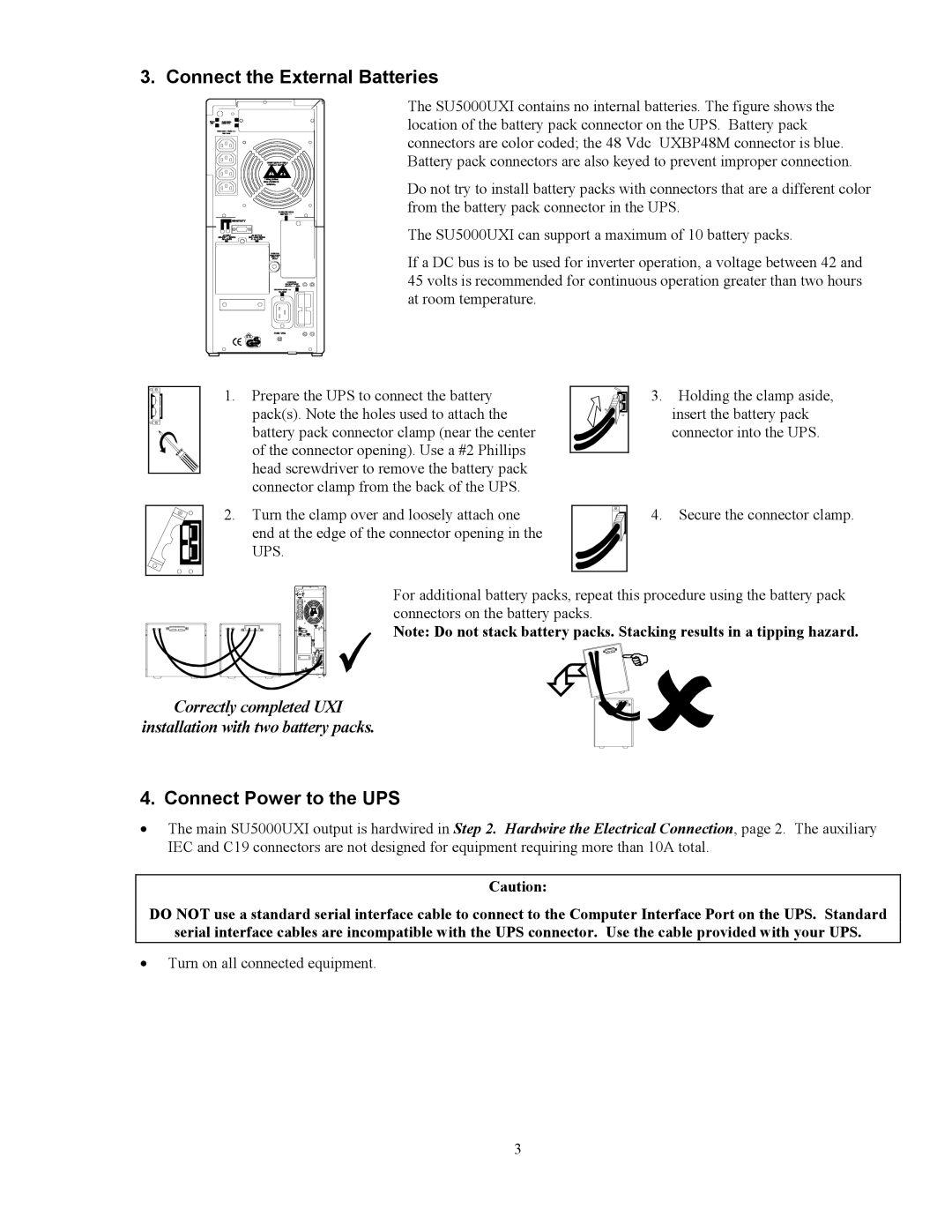
The SU5000UXI contains no internal batteries. The figure shows the location of the battery pack connector on the UPS. Battery pack connectors are color coded; the 48 Vdc UXBP48M connector is blue. Battery pack connectors are also keyed to prevent improper connection.
Do not try to install battery packs with connectors that are a different color from the battery pack connector in the UPS.
The SU5000UXI can support a maximum of 10 battery packs.
If a DC bus is to be used for inverter operation, a voltage between 42 and 45 volts is recommended for continuous operation greater than two hours at room temperature.
1.Prepare the UPS to connect the battery pack(s). Note the holes used to attach the battery pack connector clamp (near the center of the connector opening). Use a #2 Phillips head screwdriver to remove the battery pack connector clamp from the back of the UPS.
2.Turn the clamp over and loosely attach one end at the edge of the connector opening in the UPS.
3.Holding the clamp aside, insert the battery pack connector into the UPS.
4.Secure the connector clamp.
For additional battery packs, repeat this procedure using the battery pack connectors on the battery packs.
Note: Do not stack battery packs. Stacking results in a tipping hazard.
Correctly completed UXI
installation with two battery packs.
4. Connect Power to the UPS
•The main SU5000UXI output is hardwired in Step 2. Hardwire the Electrical Connection, page 2. The auxiliary IEC and C19 connectors are not designed for equipment requiring more than 10A total.
Caution:
DO NOT use a standard serial interface cable to connect to the Computer Interface Port on the UPS. Standard
serial interface cables are incompatible with the UPS connector. Use the cable provided with your UPS.
•Turn on all connected equipment.
3