|
|
|
|
| Installation |
|
|
|
|
|
|
| 1 Connect the Battery | 2 | Placement / Power |
|
|
|
|
| In compliance with Department of Transportation (DOT) regulations, the | Avoid placing the | |
| ® |
| internal red battery wire disconnected. The |
|
| ||
|
| nected to the battery. Once connected, allow the | • | Direct sunlight | |||
| ® |
|
| ||||
|
|
|
|
| Note: Small sparks may occur during battery connection. This is normal. | • | Excessive heat |
| www.apc.com |
|
| • Excessive humidity or in contact with fluids | |||
|
|
|
|
|
|
| of any type |
|
|
|
|
|
|
|
|
Back-UPS™
RS 500
Plug the
a. Open the battery compartment, as shown. | c. Connect the red battery wire to the |
|
|
| positive |
User’s Manual | battery terminal. |
|
|
| |
|
|
|
|
| |
990-2204
b. Pull the battery about half way out, as shown | d. Push the battery into the battery compartment | • The |
| and | any time it is connected to a wall outlet. |
3 | Check the Building | 4 | Connect Equipment to the |
| 5 Connect the Phone | |||||
Wiring Fault Indicator | The rear panel of the |
|
| Fax | Line to Surge Protection | |||||
If the red Building Wiring Fault indicator on the | following elements: | Monitor |
| The telephone ports provide lightning surge pro- | ||||||
|
|
|
|
| ||||||
rear panel of the | Battery Back Up Outlets (qty. of 3). These |
|
|
| tection for any device connected to the telephone | |||||
following conditions exists: | outlets provide battery | Computer |
|
| line (computer, modem, fax or telephone). The | |||||
• | Open or high resistance ground | and |
|
| telephone ports are compatible with Home Phone- | |||||
In case of power outage, battery power is |
|
| Printer | line Networking Alliance (HPNA) and Digital | ||||||
• | Hot or neutral polarity reversed | automatically provided to these outlets. Power | External |
| Suscriber Line (DSL) standards, as well as all | |||||
• | Overloaded neutral circuit | (utility or battery) is not supplied to these outlets |
|
| modem data rates. Connect as shown. | |||||
Drive |
|
| ||||||||
|
|
| when the |
|
|
|
|
| ||
A lit indicator means that a potential shock | computer, monitor, and external disk or |
|
|
|
| Wall Outlet | ||||
drive to these outlets. |
|
| Scanner |
| ||||||
hazard exists. Improper building wiring should |
|
|
|
| ||||||
be corrected by a qualified electrician. Do not | Surge Only Outlets (qty. of 3). These outlets are |
|
|
|
|
| ||||
use the |
|
|
|
|
| |||||
always On (when utility power is available) and |
|
|
|
|
| |||||
the fault is corrected. |
|
|
|
|
| |||||
are not controlled by the On/Off switch. These | Black Velcro Straps (qty. of 2 - not shown). For |
|
| |||||||
Note: Improper building wiring will not prevent the | outlets do not provide power during a power |
|
| |||||||
outage. Connect a printer, fax machine or scanner | convenience, two velcro traps have been included |
|
| |||||||
to these outlets. | and can be used to manage power cords. |
|
| |||||||
protection | capability. It may also result in |
|
|
|
|
|
|
| ||
equipment damage that is not covered by the APC |
|
|
|
|
| Modem/Phone/Fax | ||||
Equipment Protection Policy. |
|
|
|
|
| |||||
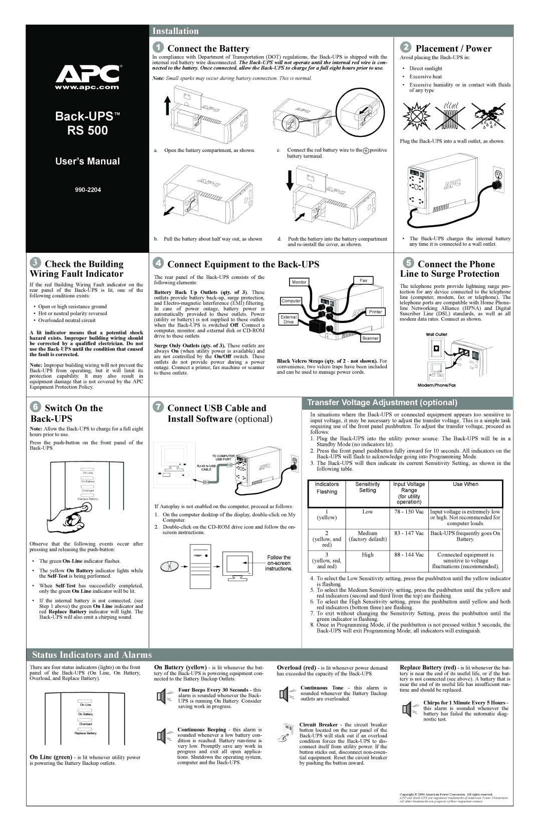
6 | Switch On the | 7 | Connect USB Cable and | Transfer Voltage Adjustment (optional) | ||||||
In situations where the | ||||||||||
|
| Install Software (optional) | ||||||||
| input voltage, it may be necessary to adjust the transfer voltage. This is a simple task | |||||||||
Note: Allow the |
|
|
| requiring use of the front panel pushbutton. To adjust the transfer voltage, proceed as | ||||||
|
|
| follows: |
|
|
| ||||
hours prior to use. |
|
|
|
|
|
| ||||
|
|
| 1. Plug the | |||||||
Press the |
|
|
| |||||||
|
|
| Standby Mode (no indicators lit). |
| ||||||
|
|
|
| 2. Press the front panel pushbutton fully inward for 10 seconds. All indicators on the | ||||||
|
|
|
| TO COMPUTER |
| |||||
|
|
|
| USB PORT |
| 3. The | ||||
|
|
|
|
| ||||||
|
|
|
|
| following table. |
|
| |||
|
| On Line |
| CABLE |
|
|
| |||
|
|
|
|
|
|
|
|
| ||
|
| On Battery |
|
|
| Indicators | Sensitivity | Input Voltage | Use When | |
|
|
|
|
|
| |||||
|
| Overload |
|
|
| Flashing | Setting | Range |
| |
|
|
|
|
|
|
|
|
| ||
|
| Replace Battery |
|
|
|
|
| (for utility |
| |
|
|
| If Autoplay is not enabled on the computer, proceed as follows: |
|
| operation) |
| |||
|
|
| 1 | Low | 78 - 150 Vac | Input voltage is extremely low | ||||
|
|
| 1. On the computer desktop of the display, | |||||||
|
|
| (yellow) |
|
| or high. Not recommended for | ||||
|
|
|
| Computer. |
|
|
| |||
|
|
|
|
|
|
|
| computer loads. | ||
|
|
| 2. |
|
|
| ||||
|
|
|
|
|
|
| ||||
|
|
|
| screen instructions. |
| 2 | Medium | 83 - 147 Vac | ||
Observe that the following events occur after |
|
|
| (yellow, and | (factory default) |
| Battery. | |||
|
|
| red) |
|
|
| ||||
pressing and releasing the |
|
|
| 3 | High | 88 - 144 Vac | Connected equipment is | |||
|
|
|
|
| Follow the | |||||
• The green |
|
| (yellow, red, |
|
| sensitive to voltage | ||||
|
|
|
| |||||||
|
|
|
|
| and red) |
|
| fluctuations (recommended). | ||
• | The yellow On Battery indicator lights while |
|
| instructions. |
|
| ||||
|
|
|
|
|
| |||||
| the |
|
|
| 4. To select the Low Sensitivity setting, press the pushbutton until the yellow indicator | |||||
• | When |
|
|
| is flashing. |
|
|
| ||
| only the green On Line indicator will be lit. |
|
|
| 5. To select the Medium Sensitivity setting, press the pushbutton until the yellow and | |||||
• | If the | internal battery is not connected, (see |
|
|
| red indicators (second and third from the top) are flashing. | ||||
|
|
| 6. To select the High Sensitivity setting, press the pushbutton until yellow and both | |||||||
| Step 1 above) the green On Line indicator and |
|
|
| red indicators (bottom three) are flashing. |
| ||||
| red Replace Battery indicator will light. The |
|
|
| 7. To exit without changing the Sensitivity Setting, press the pushbutton until the | |||||
|
|
|
| green indicator is flashing. |
|
| ||||
|
|
|
|
|
| 8. Once in Programming Mode, if the pushbutton is not pressed within 5 seconds, the | ||||
|
|
|
|
|
| |||||
Status Indicators and Alarms
There are four status indicators (lights) on the front panel of the
On Line
On Battery
Overload
Replace Battery
On Line (green) - is lit whenever utility power is powering the Battery Backup outlets.
On Battery (yellow) - is lit whenever the bat- tery of the
Four Beeps Every 30 Seconds - this alarm is sounded whenever the Back- UPS is running On Battery. Consider saving work in progress.
Continuous Beeping - this alarm is sounded whenever a low battery con- dition is reached. Battery
Overload (red) - is lit whenever power demand has exceeded the capacity of the
Continuous Tone - this alarm is sounded whenever the Battery Backup outlets are overloaded.
Circuit Breaker - the circuit breaker button located on the rear panel of the
Replace Battery (red) - is lit whenever the bat- tery is near the end of its useful life, or if the bat- tery is not connected (see above). A battery that is near the end of its useful life has insufficient run- time and should be replaced.
Chirps for 1 Minute Every 5 Hours - this alarm is sounded whenever the battery has failed the automatic diag- nostic test.
Copyright © 2004 American Power Conversion. All rights reserved.
APC and