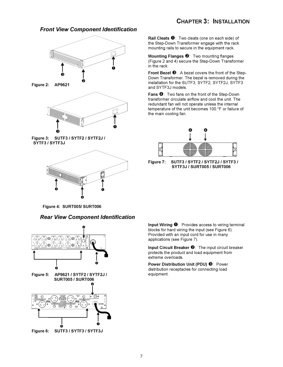
SYTF3, SYTF3J, SYTF2, SURT005, AP9621 specifications
American Power Conversion (APC) has built a formidable reputation in the field of power protection and management solutions, with a portfolio that includes a diverse range of Uninterruptible Power Supplies (UPS). Among those, the SURT006, SURT005, SYTF2, SYTF2J, and SYTF3 units stand out due to their exceptional features and advanced technologies.The APC SURT006 and SURT005 are part of the Smart-UPS On-Line series. They are designed for high-demand applications, providing robust power backup and conditioning. The SURT006, featuring a capacity of 6 kVA, delivers reliable power for critical hardware, ensuring continuity during outages. Similarly, the SURT005 with a 5 kVA rating serves smaller setups efficiently. Both models utilize double-conversion technology, meaning they convert incoming AC power to DC, and then back to AC. This process guarantees that devices are supplied with clean and stable power, free from surges, sags, and noise.
Equipped with an intelligent control system, these UPS units offer scalable runtime and connectivity options. They feature an advanced LCD interface that provides real-time monitoring of power conditions, battery status, and system functions. The ability to configure settings via the user-friendly display simplifies management in diverse environments.
The SYTF2, SYTF2J, and SYTF3 models cater to different operational needs and environments. These units are designed with network administrators in mind, offering seamless support for data centers, voice and data applications, and complex IT systems. The SYTF series benefits from hot-swappable batteries, which ensure that maintenance can be conducted without disrupting operations. Furthermore, advanced thermal management and intelligent fan control improve efficiency while prolonging battery life.
A common feature across the SYTF series is their integration with software for power management and monitoring. This provides valuable insights into energy consumption, battery health, and overall system performance, empowering users to make data-driven decisions. The models are also compatible with APC's award-winning PowerChute management software, enhancing the capabilities of the UPS by allowing remote monitoring and configuration.
The APC SURT006, SURT005, SYTF2, SYTF2J, and SYTF3 are exemplary solutions for businesses requiring uninterrupted power supply and stringent power quality standards. With features like robust battery management, surge protection, and intelligent control systems, they meet the rigorous demands of modern critical infrastructure. These UPS solutions stand ready to support any environment, ensuring that businesses maintain operational uptime and efficiency.

