
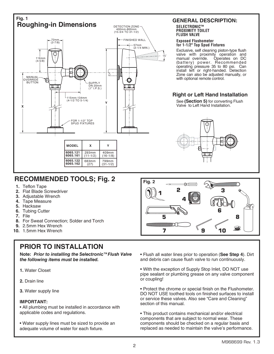
6065.162, 6065.122, 6065.121, 6065.565, 6065.161 specifications
The American Standard values quality, durability, and innovation in its bath and toilet products. Among its notable offerings are the models 6065.565, 6065.162, 6065.121, 6065.161, and 6065.122. Each model showcases unique features and technologies that cater to diverse consumer needs.The American Standard 6065.565 is designed with a modern aesthetic that suits any bathroom décor while ensuring functionality is not compromised. It typically features a spacious bathing well, allowing for maximum comfort. Its acrylic construction ensures a lightweight build without sacrificing durability, making it resistant to cracking and chipping. Additionally, it incorporates slip-resistant surfaces, enhancing safety for users of all ages.
Model 6065.162 offers a different take with its focus on water efficiency and sustainability. This shower model integrates advanced flow control technology, which optimizes water usage without sacrificing performance. Its ergonomic design provides a luxurious showering experience while advocating for environmental responsibility. The easy-to-clean surfaces also reduce maintenance time, allowing users to enjoy their showers without the hassle of extensive upkeep.
The 6065.121 is tailored for those seeking a modern tub design with added features. This model comes with an integrated bathing ledge, allowing for relaxation with added convenience. It is equipped with an adjustable showerhead and hand shower combination, enabling users to customize their shower experience. The tub is constructed from high-quality fiberglass, enhancing durability and insulation, ensuring water stays warm for longer periods.
Moving on to the 6065.161, this model emphasizes ergonomic design coupled with functionality. With a wide profile and deep basin, it is ideal for soaking. Advanced drainage technology ensures quick water removal, allowing for an uninterrupted bathing experience. The model’s sleek lines and minimalist appearance resonate well with contemporary design trends, making it a popular choice among homeowners.
Finally, the 6065.122 caters to those who appreciate versatility. This model can seamlessly transition from a traditional bath to a contemporary shower setup. Its quick-dry materials ensure minimal water pooling, maintaining a clean and safe environment. The design also includes built-in storage options, making it a practical solution for bathroom organization.
Together, these American Standard models exemplify the brand's commitment to innovative design and performance in the bathroom space. Whether it's prioritizing comfort, sustainability, or versatility, each model serves as a testament to American Standard’s dedication to enhancing the daily rituals of bathing.