6
BOLT CAP
WASHER
NUT
BOLTS
CLOSET BOLT
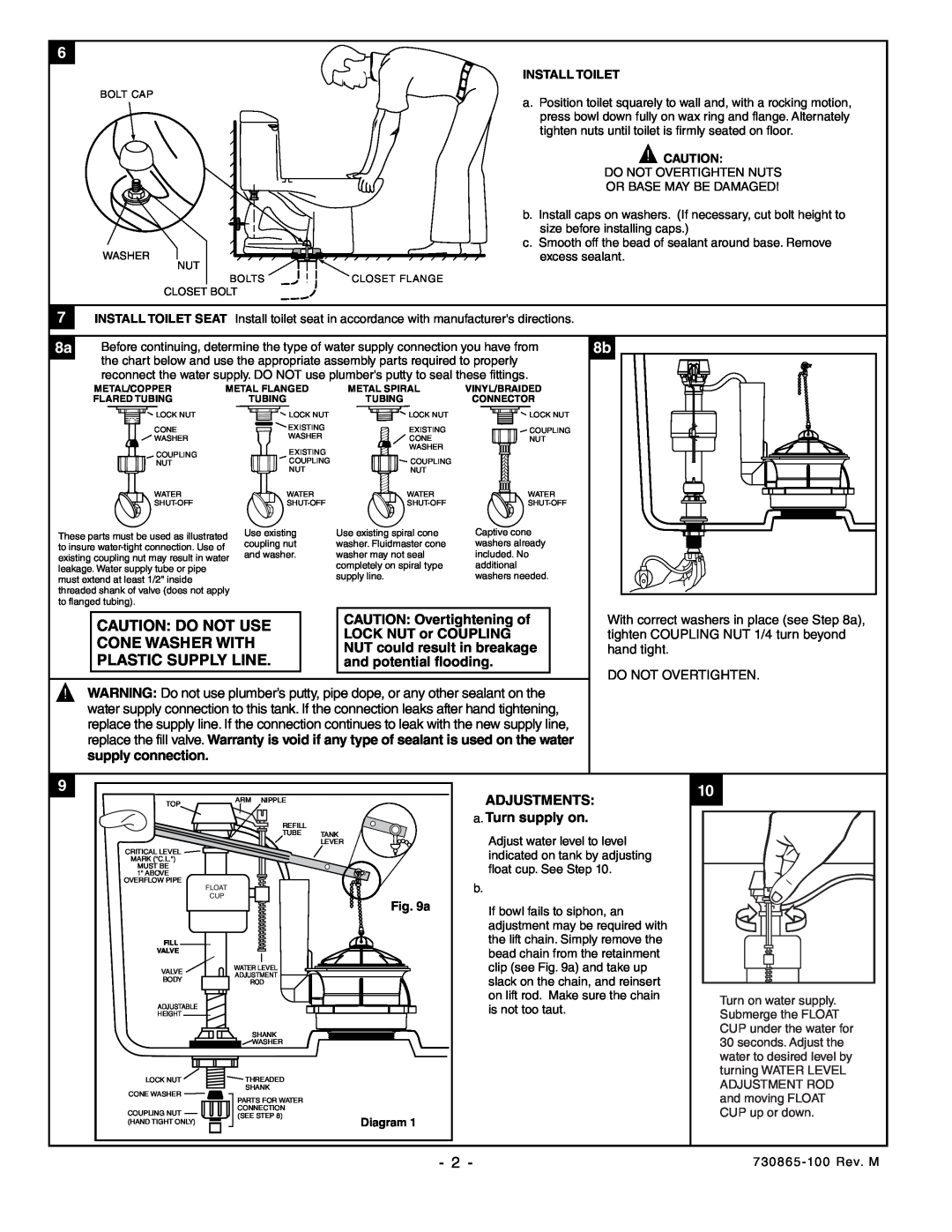
INSTALL TOILET
a. Position toilet squarely to wall and, with a rocking motion, press bowl down fully on wax ring and flange. Alternately tighten nuts until toilet is firmly seated on floor.
! CAUTION:
DO NOT OVERTIGHTEN NUTS
OR BASE MAY BE DAMAGED!
b.Install caps on washers. (If necessary, cut bolt height to size before installing caps.)
c.Smooth off the bead of sealant around base. Remove
excess sealant.
CLOSET FLANGE
7 INSTALL TOILET SEAT Install toilet seat in accordance with manufacturer's directions.
8a | Before continuing, determine the type of water supply connection you have from |
| the chart below and use the appropriate assembly parts required to properly |
|
reconnect the water supply. DO NOT use plumber's putty to seal these fittings.
8b
METAL/COPPER | METAL FLANGED | METAL SPIRAL | ||
FLARED TUBING |
| TUBING | TUBING | |
LOCK NUT |
| LOCK NUT | LOCK NUT | |
CONE |
| EXISTING | EXISTING | |
| WASHER | |||
WASHER |
| CONE | ||
COUPLING |
| EXISTING | WASHER | |
|
| |||
| COUPLING | COUPLING | ||
NUT |
| |||
|
| NUT | NUT | |
WATER |
| WATER | WATER | |
| ||||
These parts must be used as illustrated | Use existing | Use existing spiral cone | ||
coupling nut | washer. Fluidmaster cone | |||
to insure |
| |||
| and washer. | washer may not seal | ||
existing coupling nut may result in water | ||||
leakage. Water supply tube or pipe | completely on spiral type | |
supply line. | ||
must extend at least 1/2" inside | ||
| ||
threaded shank of valve (does not apply |
| |
to flanged tubing). |
|
VINYL/BRAIDED
CONNECTOR
![]() LOCK NUT
LOCK NUT
![]() COUPLING
COUPLING
NUT
WATER
Captive cone washers already included. No additional washers needed.
|
| CAUTION: Overtightening of |
CAUTION: DO NOT USE |
| |
| LOCK NUT or COUPLING | |
CONE WASHER WITH |
| |
| NUT could result in breakage | |
PLASTIC SUPPLY LINE. |
| and potential flooding. |
!WARNING: Do not use plumber’s putty, pipe dope, or any other sealant on the water supply connection to this tank. If the connection leaks after hand tightening, replace the supply line. If the connection continues to leak with the new supply line, replace the fill valve. Warranty is void if any type of sealant is used on the water supply connection.
With correct washers in place (see Step 8a), tighten COUPLING NUT 1/4 turn beyond hand tight.
DO NOT OVERTIGHTEN.
9
TOP | ARM | NIPPLE |
|
|
|
| |
|
| REFILL |
|
|
| TUBE | TANK |
|
|
| LEVER |
CRITICAL LEVEL |
|
|
|
MARK ("C.L.") |
|
|
|
MUST BE |
|
|
|
1" ABOVE |
|
|
|
OVERFLOW PIPE | FLOAT |
|
|
|
|
| |
| CUP |
| Fig. 9a |
|
|
| |
FILL |
|
|
|
VALVE |
|
|
|
VALVE | WATER LEVEL |
| |
ADJUSTMENT |
| ||
BODY |
| ||
ROD |
| ||
|
| ||
ADJUSTABLE |
|
|
|
HEIGHT |
|
|
|
SHANK
![]()
![]()
![]() WASHER
WASHER
LOCK NUT | THREADED | |
CONE WASHER | SHANK | |
PARTS FOR WATER | ||
| ||
COUPLING NUT | CONNECTION | |
(SEE STEP 8) | ||
(HAND TIGHT ONLY) | Diagram 1 |
ADJUSTMENTS: a. Turn supply on.
Adjust water level to level indicated on tank by adjusting float cup. See Step 10.
b.
If bowl fails to siphon, an adjustment may be required with the lift chain. Simply remove the bead chain from the retainment clip (see Fig. 9a) and take up slack on the chain, and reinsert on lift rod. Make sure the chain is not too taut.
10
Turn on water supply. Submerge the FLOAT CUP under the water for 30 seconds. Adjust the water to desired level by turning WATER LEVEL ADJUSTMENT ROD and moving FLOAT CUP up or down.
- 2 - |