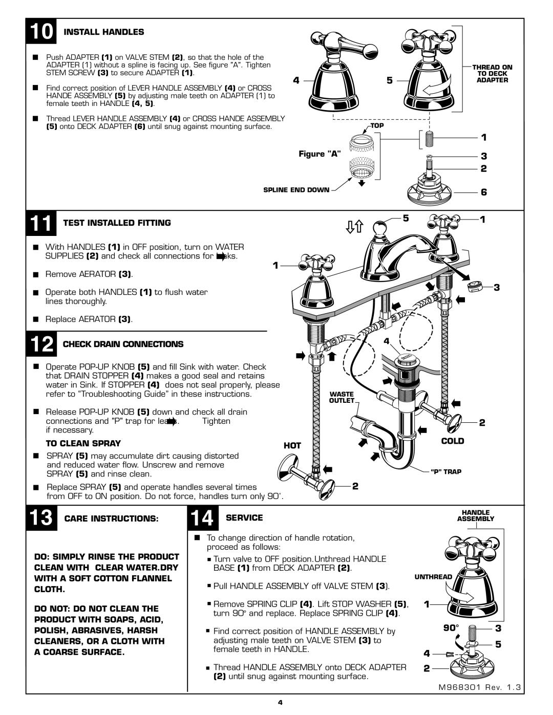
10 INSTALL HANDLES
Push ADAPTER (1) on VALVE STEM (2), so that the hole of the |
|
ADAPTER (1) without a spline is facing up. See figure "A". Tighten |
|
STEM SCREW (3) to secure ADAPTER (1). | 5 |
4 | |
Find correct position of LEVER HANDLE ASSEMBLY (4) or CROSS |
|
HANDE ASSEMBLY (5) by adjusting male teeth on ADAPTER (1) to female teeth in HANDLE (4, 5).
THREAD ON
TO DECK
ADAPTER
Thread LEVER HANDLE ASSEMBLY (4) or CROSS HANDE ASSEMBLY | TOP |
| |
(5) onto DECK ADAPTER (6) until snug against mounting surface. |
| ||
|
|
| 1 |
| Figure "A" |
| 3 |
|
|
| 2 |
| SPLINE END DOWN |
| 6 |
|
|
| |
11 TEST INSTALLED FITTING |
| 5 | 1 |
|
|
| |
With HANDLES (1) in OFF position, turn on WATER |
|
| |
SUPPLIES (2) and check all connections for | . |
|
|
Remove AERATOR (3). | 1 |
|
|
|
|
| |
Operate both HANDLES (1) to flush water |
|
| 3 |
|
|
| |
lines thoroughly. |
|
|
|
Replace AERATOR (3). |
|
|
|
12 CHECK DRAIN CONNECTIONS |
| 4 | |
|
| ||
Operate |
| ||
that DRAIN STOPPER (4) makes a good seal and retains |
| ||
water in Sink. If STOPPER (4) | does not seal properly, please |
| |
refer to “Troubleshooting Guide” in these instructions. | WASTE | ||
|
|
| OUTLET |
Release |
| ||
connections and "P" trap for | . | Tighten |
|
if necessary. |
|
|
|
TO CLEAN SPRAY |
|
| HOT |
SPRAY (5) may accumulate dirt causing distorted |
| ||
and reduced water flow. Unscrew and remove |
| ||
SPRAY (5) and rinse clean. |
|
|
|
Replace SPRAY (5) and operate handles several times | 2 | ||
from OFF to ON position. Do not force, handles turn only 90˚.
2
COLD
![]() “P” TRAP
“P” TRAP
13 CARE INSTRUCTIONS:
DO: SIMPLY RINSE THE PRODUCT CLEAN WITH CLEAR WATER.DRY WITH A SOFT COTTON FLANNEL CLOTH.
DO NOT: DO NOT CLEAN THE PRODUCT WITH SOAPS, ACID, POLISH, ABRASIVES, HARSH CLEANERS, OR A CLOTH WITH A COARSE SURFACE.
14 SERVICE | HANDLE |
| |
ASSEMBLY |
| ||
To change direction of handle rotation, |
|
| |
proceed as follows: |
|
| |
Turn valve to OFF position.Unthread HANDLE |
|
| |
BASE (1) from DECK ADAPTER (2). |
|
| |
| UNTHREAD |
| |
Pull HANDLE ASSEMBLY off VALVE STEM (3). |
|
| |
Remove SPRING CLIP (4). Lift STOP WASHER (5), | 1 |
| |
turn 90° and replace. Replace SPRING CLIP (4). |
|
| |
Find correct position of HANDLE ASSEMBLY by | 90° | 3 | |
adjusting male teeth on VALVE STEM (3) to |
| 5 | |
female teeth in HANDLE. | 4 | ||
| |||
|
| ||
Thread HANDLE ASSEMBLY onto DECK ADAPTER | 2 |
| |
(2) until snug against mounting surface. |
|
| |
| M968301 Rev. 1 . 3 | ||
4