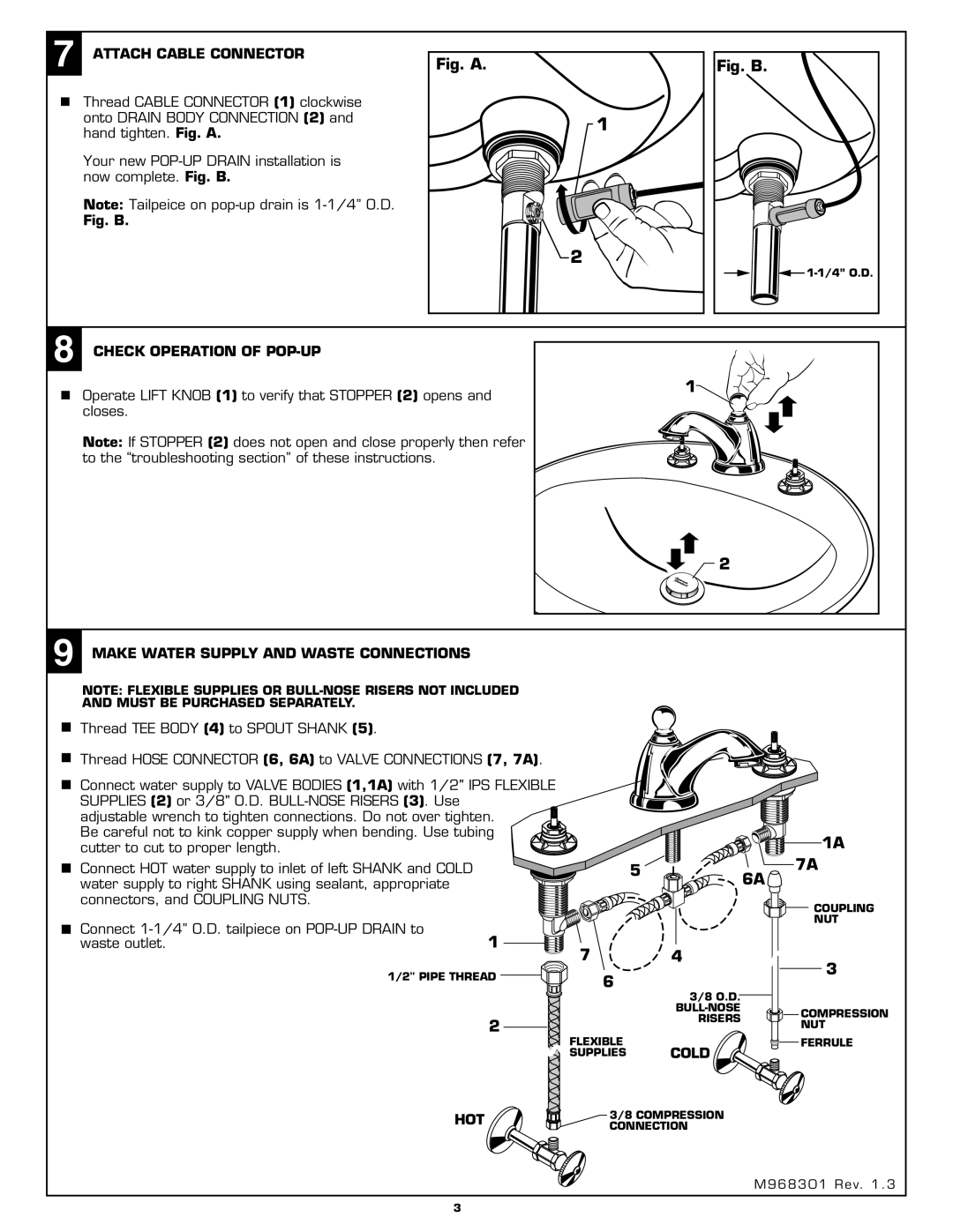
7ATTACH CABLE CONNECTOR
Thread CABLE CONNECTOR (1) clockwise onto DRAIN BODY CONNECTION (2) and hand tighten. Fig. A.
Your new
Note: Tailpeice on
Fig. B.
Fig. A.
1
![]() 2
2
Fig. B.
![]()
8 CHECK OPERATION OF |
|
Operate LIFT KNOB (1) to verify that STOPPER (2) opens and | 1 |
| |
closes. |
|
Note: If STOPPER (2) does not open and close properly then refer to the “troubleshooting section” of these instructions.
2
9MAKE WATER SUPPLY AND WASTE CONNECTIONS
NOTE: FLEXIBLE SUPPLIES OR
Thread TEE BODY (4) to SPOUT SHANK (5).
Thread HOSE CONNECTOR (6, 6A) to VALVE CONNECTIONS (7, 7A).
Connect water supply to VALVE BODIES (1,1A) with 1/2" IPS FLEXIBLE SUPPLIES (2) or 3/8" O.D.
adjustable wrench to tighten connections. Do not over tighten. Be careful not to kink copper supply when bending. Use tubing cutter to cut to proper length.
Connect HOT water supply to inlet of left SHANK and COLD water supply to right SHANK using sealant, appropriate connectors, and COUPLING NUTS.
Connect | 1 |
| |
waste outlet. |
| 7 | |
|
|
| |
| 1/2" PIPE THREAD | 6 | |
|
|
| |
|
| 2 | FLEXIBLE |
|
|
| |
|
|
| SUPPLIES |
|
| 1A |
5 |
| 7A |
| 6A | |
|
| |
|
| COUPLING |
|
| NUT |
| 4 | 3 |
|
| |
| 3/8 O.D. |
|
| COMPRESSION | |
| RISERS | |
| NUT | |
|
| |
| COLD | FERRULE |
|
|
HOT | 3/8 COMPRESSION |
| CONNECTION |
M968301 Rev. 1 . 3
3