Software Version December
Page
Copyright 2002, Cisco Systems, Inc All rights reserved
Page
N T E N T S
Mid-Mounting the CSS 11506 Mounting Brackets
Powering Up the CSS
Cable Connector Pinouts B-1
Troubleshooting C-1
Radiation from Open Port Aperture Warning
D E
Xii
Front-Mounting Position of the CSS 11506 Mounting Brackets
Location of the CSS 11506 Power Supplies C-13
RJ-45 Fast Ethernet Connector Pinouts B-2
Table B-3
Audience
About This Guide
Chapter/Appendix Description
How to Use This Guide
Document Title Description
Related Documentation
Document Title Description
Xxi
Symbols and Conventions
Xxii
Xxiii
World Wide Web
Obtaining Documentation
Ordering Documentation
Documentation CD-ROM
Documentation Feedback
You can order Cisco documentation in these ways
Cisco.com
Obtaining Technical Assistance
Technical Assistance Center
Priority level 4 P4 product capabilities
Cisco TAC Web Site
Cisco TAC Escalation Center
Unpacking and Installing the CSS
Site Requirements
Safety Guidelines
Chassis-Lifting Guidelines for the CSS 11503 and CSS
Electrical Safety
Unpacking and Installing the CSS Safety Guidelines
AC Specification CSS
Specifications for Cisco 11500 Series Power Supplies
DC Specification CSS
Required Tools and Equipment
Power Guidelines for DC Systems CSS 11503 and CSS
Shipment Contents
Unpacking the CSS
Unpacking the CSS
Unpacking the CSS 11503 or CSS
If the Product is Damaged
Preinstallation Requirements
Installing a CSS 11501 as a Freestanding Unit
Installing the CSS
2illustrates front-mounting the mounting brackets
Installing a CSS 11501 as a Rackmounted Unit
Installing a CSS 11503 as a Freestanding Unit
59538
Installing a CSS 11503 as a Rackmounted Unit
Mid-Mounting the Mounting Brackets on the CSS
Front-Mounting Position of the CSS 11506 Mounting Brackets
Mid-Mounting the CSS 11506 Mounting Brackets
Rack-Mounting the CSS 11506 Chassis
Installing a CSS Module
Installation Precautions
Installation Precautions and Restrictions
Module Slot Restrictions
Initial active Switch Control Module SCM
Slot Number Slot Usage
Module
Slot location
Slot location
59550
Unpacking a CSS Module
Installing a Module
Installing a Module into a CSS Chassis
Installing a Passive SCM in a CSS
Installing a Pcmcia Cover on an SCM
Unpacking and Installing the CSS Installing a CSS Module
Cabling the CSS
Cabling the CSS
Cabling the CSS
CSS 11501 Connectors and LEDs
CSS 11501 Connectors and LEDs
LED Name Color State Indicates
1describes the CSS 11501 LEDs and their indications
LED Name Color State Indicates
CSS 11503 and CSS 11506 Module Overview
Cabling the CSS 11503 and CSS 11506 Modules
Cabling the CSS Cabling the CSS 11503 and CSS 11506 Modules
2illustrates a fully-configured CSS 11503 and its components
3illustrates a fully-configured CSS 11506 and its components
Switch Control Module Connectors and LEDs
11b
11a
2describes the SCM LEDs and their indications
10BASE-T/100BASE-TX connector
Fast Ethernet Module Connectors and LEDs
RJ-45 Ethernet
16-Port Fast Ethernet Module Connectors and LEDs
3describes the FEM LEDs and their indications
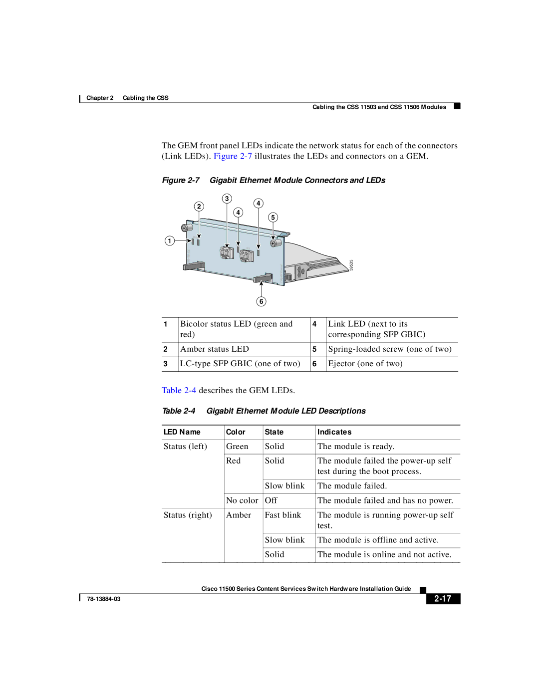
Gigabit Ethernet Module Connectors and LEDs
Gigabit Ethernet Module Connectors and LEDs
8illustrates the SAM front panel LEDs
Session Accelerator Module LEDs
5describes the LEDs
Secure Socket Layer SSL Module LEDs
9illustrates the SSL module front panel LEDs
Parameters Default Settings
Connecting the Console
Baud 9600 Data Bits Parity None Stop Bits Terminal Type
Flow Control None
Tools and Supplies
Connecting the Chassis to Ground
Quantity Description Comments
Connecting the Chassis to Ground
Lug Strip Length
Attaching the Grounding Cable
Go to the next section, Connecting the Power Cord
Connecting a CSS 11501 Power Cord
Connecting the Power Cord
AC power connector Power switch
Connecting a CSS 11503 AC Power Cord
Connecting a CSS 11503 Power Cord
Power switch AC power connector
Following sections provide information on
Connecting a CSS 11503 DC Power Cord
13 Location of the CSS 11503 DC Power Supply Connectors
Terminal block -, +, Power switch
Ground
CSS DC Power Source
Connecting a CSS 11506 AC Power Cord
Connecting a CSS 11506 Power Cord
14 Connecting a CSS 11506 AC Power Cord
Connecting a CSS 11506 DC Power Cord
OK OK
Power supply LEDs Power switch Terminal block -, +,
10 CSS 11506 to DC Power Source Cabling
Checking the DC Power Connection CSS 11503 and CSS
Powering Up the CSS
Booting and Configuring the CSS
Booting the CSS for the First Time
Powering Down the CSS
Hardware Initialization and Power-On Diagnostics
State Sequence LED Color LED State
Entering Your License Key
At the prompt, enter the 12-digit option license key
Configuring the Ethernet Management Port
CSS allows you to change the default username and password
Changing the Default Username and Password
No to keep the default username and password
Password-Protecting the Offline Diagnostic Monitor Menu
Logging in to the CSS
CSS then enables you to access the OffDM menu
Using the Configuration Script
192.168.3.3
Configuring Layer 3 Load Balancing
To configure Layer 3 load balancing, enter
Configuring Layer 5 Load Balancing
192.168.3.8
Configuring Proxy Cache
192.168.3.9
Configuring Transparent Cache
78-13884-03
Service TransparentCache1
Video/x-msvideo
Where to Go Next
78-13884-03
Specifications
Electrical Specifications
Specification Operating Non-operating
Environmental Specifications
Specification CSS
Physical Specifications
Disk Specifications
Module Specifications
Specification Hard Disk Flash Disk
Capacity minimum 512 MB 256 MB Interface
Supported Standards
Address Resolution Protocol ARP Inverse ARP
Transport
Network
Gateway
Routing
Application
Network Utilities
Network Management
Cable Connector Pinouts
Signal Name Numbers
RJ-45 Fast Ethernet Connector Pinouts
RJ-45 Fast Ethernet Pin
RX + TX + Unconnected
RJ-45 RS-232 Console Port Pinouts
Signal Name Pin Number
Following sections provide the pinouts for
RJ-45 Rollover
Connecting the Console Port to a PC
RJ-45 Rollover DB-25 DTE
Connecting the Console Port to a Terminal
RJ-45 Rollover DB-25 DCE
Connecting the Console Port to a Modem
TX + RX + Unconnected
RJ-45 Management Connector Pinouts
78-13884-03
Troubleshooting
Diagnostic Tests for Hardware
Troubleshooting the Boot Process
For information about the boot process, refer to , Booting
Test Ref # Testreference
Field Description
Field Description
Field Description
Provides information about the error for example
Errors in the Boot Configuration Record
Failure of the Disk Drive in the SCM
CSS 11501 Boot and Verification
SCM Boot and Verification of the Modules
Possible Problem Recommended Action
Troubleshooting the Console Interface
Troubleshooting the CSS 11501 Power Supply
Troubleshooting the CSS Power Supply
Following sections discuss
Troubleshooting the CSS 11506 Power Supply
Troubleshooting the CSS 11503 Power Supply
59603
Power supply
Power Supply LEDs I/P OK and 3 Terminal block
Power Supply LEDs AC OK and 3 AC connector
DC OK
LED State AC OK or
Troubleshooting the CSS 11501 Chassis Fans
Troubleshooting the CSS Fans
When a fan failure occurs, you must replace the CSS chassis
Troubleshooting the CSS 11503 Chassis Fans
Troubleshooting the CSS 11506 Fan Module
Symptom Recommended Action
Troubleshooting the CSS
Symptom Recommended Action
Troubleshooting the CSS Modules
Chassis command to verify the state
Power up the CSS to boot the module
Reboot the CSS to boot the module
Modules
Temperature that is too high, indicated by Variable
Log File Information
Log File Destination Default Alternate Location Records
Log file when a system log file is
Overwrites an existing backup system
Renamed. When you reboot a CSS,
Size 50 MB, for a hard disk-based
Appendix C Troubleshooting Log File Information
This appendix includes the following sections
Regulatory
Agency Approvals
Approval Agency and Requirement
FCC Class a Compliance Notice United States
+408
FCC Compliance Information Statement United States
Europe EU
ICES-003 Class a Compliance Notice Canada
Cispr 22 Class a Warning
English Statement of Compliance
Vcci Class a Warning
78-13884-03
Agency Approvals
Canada
Safety Requirements
Europe
Mexico
EN60825-1 EN60825-2
Laser Safety
International
IEC60825-1 IEC60825-2
Translated Safety Warnings
Translated Safety Warnings
Lithium Battery Disposal Warning
Radiation from Open Port Aperture Warning
78-13884-03
Qualified Personnel Warning
Class 1 Laser Product Warning
Two-Person Lifting Warning
Translated Safety Warnings
Lightning Activity Warning
Jewelry Removal Warning
Reading Instructions Warning
Disconnect Device Warning
Chassis Installation Warning
Monteringsskruene
Eine dritte Person die Befestigungsschrauben festzieht
Pessoa para apertar os parafusos de montagem
Persona para ajustar los tornillos de montaje
Ground Conductor Warning
Installation and Replacement Warning
Use Copper Conductors Only
Short-Circuit Protection Warning
Wire Preparation Warning
Translated Safety Warnings
DC Power Source Warning
Translated Safety Warnings
Dual Power Supply Warning
DC Power Supply Wiring Warning
78-13884-03
Blank Faceplate Requirement Warning
78-13884-03
Power Off Before Working on System Warning
Fan Injury Warning
AC and DC Power Module Warning
Power Cord Warning other versions available
Ground Conductor Warning
78-13884-03
78-13884-03
D E
IN-2
IN-3
IN-4
IN-5
IN-6