Chapter 2 Cabling the CSS
Cabling the CSS 11501
CSS 11501 Connectors and LEDs
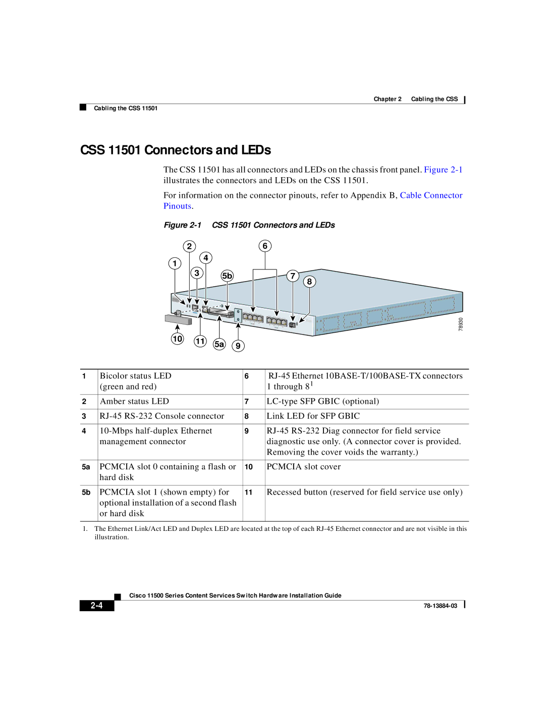
The CSS 11501 has all connectors and LEDs on the chassis front panel. Figure
For information on the connector pinouts, refer to Appendix B, Cable Connector Pinouts.
Figure 2-1 CSS 11501 Connectors and LEDs
2 |
| 6 |
1 | 4 |
|
|
| |
3 | 5b | 7 |
|
| 8 |
| STATUS | LINK/ACT |
|
|
|
|
|
|
|
|
|
|
|
|
|
|
|
|
|
| DUPLEX |
|
|
|
|
|
|
|
|
|
|
|
|
|
|
| |
|
| CONSOLE |
| LINK DPLX | LINK DPLX | LINK |
|
|
|
|
|
|
|
|
|
|
|
|
|
|
|
| DPLX | LINK DPLX |
|
|
|
|
|
|
|
|
|
| |||
|
|
|
|
|
|
|
| LINK | LINK DPLX |
|
|
|
|
|
|
|
| |
|
|
|
|
|
|
|
| DPLX | LINK DPLX | LINK |
| CIS | O |
|
| 78930 | ||
|
|
| PCMCIA |
|
|
|
|
|
|
| DPLX | 11500 |
| |||||
|
|
|
| 1 | 2 |
|
|
|
|
|
|
|
| C O | T | SERIES |
| |
|
|
|
|
| 3 |
| 4 |
|
|
|
| GE | LINK |
| I C E S | S W I T C H |
| |
|
|
|
|
| 10/100 |
|
|
|
|
|
|
|
|
|
|
| ||
|
|
|
|
|
|
|
| 5 | 6 |
| 7 |
|
|
|
|
|
|
|
|
|
|
|
|
|
|
|
|
| 8 |
|
|
|
|
|
| ||
|
|
|
|
|
|
|
|
|
| 10/100 |
|
|
|
|
|
| ||
10 |
| 11 | 5a | 9 |
|
|
|
|
|
|
|
|
|
|
|
|
|
|
|
|
|
|
|
|
|
|
|
|
|
|
|
|
|
| |||
|
|
|
|
|
|
|
|
|
|
|
|
|
|
|
|
| ||
1 | Bicolor status LED | 6 | |
| (green and red) |
| 1 through 81 |
2 | Amber status LED | 7 | |
|
|
|
|
3 | 8 | Link LED for SFP GBIC | |
|
|
|
|
4 | 9 | ||
| management connector |
| diagnostic use only. (A connector cover is provided. |
|
|
| Removing the cover voids the warranty.) |
|
|
|
|
5a | PCMCIA slot 0 containing a flash or | 10 | PCMCIA slot cover |
| hard disk |
|
|
|
|
|
|
5b | PCMCIA slot 1 (shown empty) for | 11 | Recessed button (reserved for field service use only) |
| optional installation of a second flash |
|
|
| or hard disk |
|
|
|
|
|
|
1.The Ethernet Link/Act LED and Duplex LED are located at the top of each
Cisco 11500 Series Content Services Switch Hardware Installation Guide
| ||
|