Chapter 1 Unpacking and Installing the CSS
Installing the CSS 11501
Installing a CSS 11501 as a Rackmounted Unit
Before you begin, you need the mounting brackets and the 12 Phillips screws shipped in the accessory kit accompanying the CSS 11501, and a #2 Phillips screwdriver.
To install the mounting brackets on the CSS 11501 chassis:
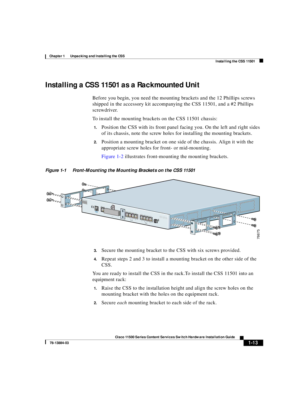
1.Position the CSS with its front panel facing you. On the left and right sides of its chassis, note the screw holes for installing the mounting brackets.
2.Position a mounting bracket on one side of the chassis. Align it with the appropriate screw holes for front- or
Figure 1-2 illustrates front-mounting the mounting brackets.
Figure 1-1 Front-Mounting the Mounting Brackets on the CSS 11501
STATUS | LINK/ACT |
|
|
|
|
|
|
|
|
|
|
|
|
|
|
| DUPLEX |
|
|
|
|
|
|
|
|
|
|
|
|
| |
| CONSOLE | LINK DPLX | LINK DPLX | LINK DPLX |
|
|
|
|
|
|
|
|
|
| |
|
| LINK DPLX |
|
|
|
|
|
|
|
|
| ||||
|
|
|
|
|
|
|
|
|
|
|
|
|
|
| |
|
|
|
|
|
| LINK DPLX | LINK DPLX | LINK |
|
|
|
|
|
|
|
|
|
|
|
|
|
| DPLX | LINK DPLX |
| CISCO |
|
|
| ||
|
| PCMCIA |
|
|
|
|
|
|
|
| S11500E |
|
| ||
|
| 1 | 2 |
|
|
|
|
|
|
| GE | C O NT EN T | SERIES | ||
|
|
|
| 3 | 4 |
|
|
|
| LINK | RV I C E S | S W I | TC H | ||
|
|
|
| 10/100 |
|
|
|
|
|
|
|
|
| ||
|
|
|
| 5 | 6 |
|
|
|
|
|
|
|
| ||
|
|
|
|
|
|
| 7 |
| 8 |
|
|
|
|
| |
|
|
|
|
|
|
| 10/100 |
|
|
|
|
|
| ||
|
|
|
|
|
|
|
|
|
|
|
|
|
| ||
78675
3.Secure the mounting bracket to the CSS with six screws provided.
4.Repeat steps 2 and 3 to install a mounting bracket on the other side of the CSS.
You are ready to install the CSS in the rack.To install the CSS 11501 into an equipment rack:
1.Raise the CSS to the installation height and align the screw holes on the mounting bracket with the holes on the equipment rack.
2.Secure each mounting bracket to each side of the rack.
Cisco 11500 Series Content Services Switch Hardware Installation Guide
| ||
|