Chapter 2 Cabling the CSS
Connecting the Power Cord
Warning Only a DC power source that is isolated from AC mains with reinforced insulation, and that complies with the other safety
Warning This unit might have more than one power supply connection; all connections must be removed completely for you to completely remove power from the unit.
To connect each CSS 11506 DC power supply to a power source:
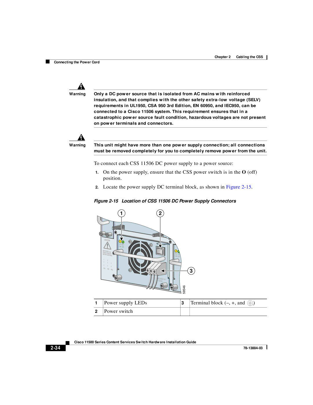
1.On the power supply, ensure that the CSS power switch is in the O (off) position.
2.Locate the power supply DC terminal block, as shown in Figure
Figure 2-15 Location of CSS 11506 DC Power Supply Connectors
![]() 1
1
S S 5 - 1 0 M - 2 G E
| CAUTION |
| ||
|
|
| I/P DC | |
|
|
| OK OK | |
DISCONN |
| |||
POWER | ECT ALL | |||
SOURCES | ||||
B |
| |||
| EFORE |
| ||
|
| SERVICING | ||
| 7 | 8 |
| |
| 1 | 2 | 3 | |
| 4 |
| ||
| 5 | 6 | ||
| PS1 |
| ||
| PS2 | PS3 | ||
|
|
| ||
GE 1 | LINK | 2 | 1 | 2 | 3 |
| GE 2 | LINK |
|
| |
|
|
|
| ||
|
| Ethernet |
|
| |
|
| igabit |
|
| |
|
|
| AC DC |
| |
|
|
| OK OK |
| |
|
|
|
|
| 3 |
|
|
|
|
| |
|
| 10/8A |
|
|
|
|
|
|
|
| 59546 |
1
2
Power supply LEDs
Power switch
3
Terminal block (–, +, and
![]() 59199)
59199)
| Cisco 11500 Series Content Services Switch Hardware Installation Guide |