HCD-C5
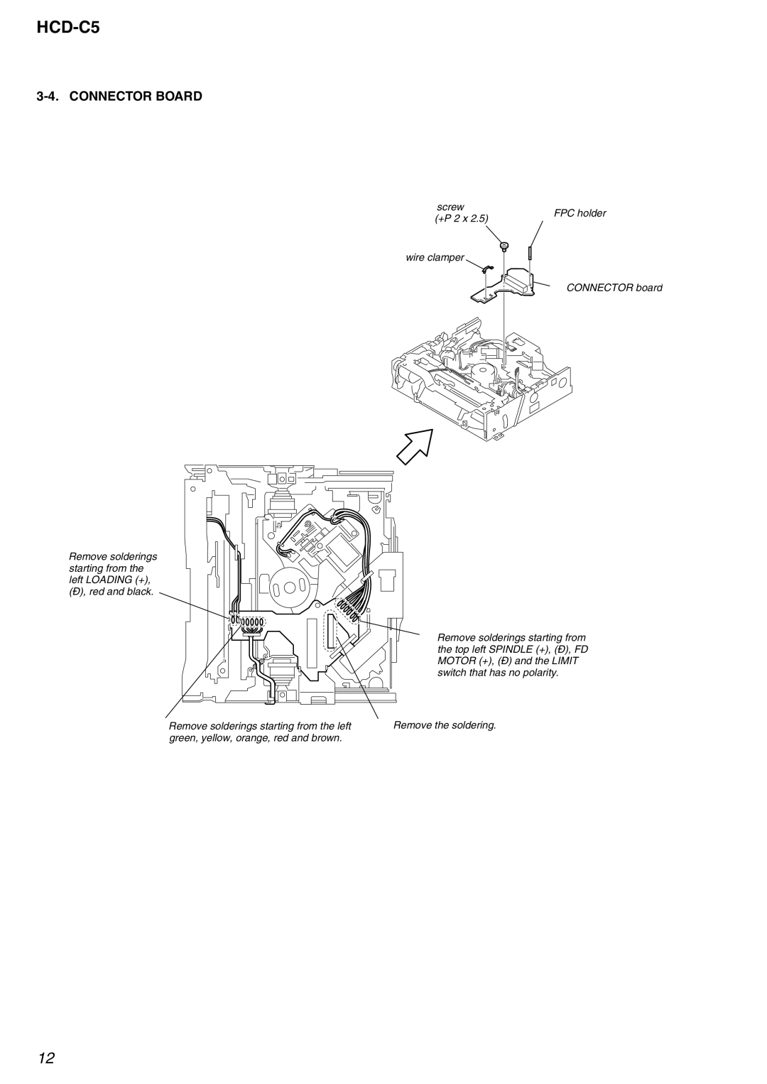
3-4. CONNECTOR BOARD
6 screw | 5 FPC holder | |
(+P 2 x 2.5) | ||
|
7 wire clamper
8 CONNECTOR board
1 Remove solderings starting from the left LOADING (+),
3 Remove solderings starting from the top left SPINDLE (+),
2 Remove solderings starting from the left | 4 Remove the soldering. |
green, yellow, orange, red and brown. |
|
12
