5. USING THE CONTINUOUSLY RECORDED DISC
*This disc is used in focus bias adjustment and error rate check. The following describes how to create a continuous recording disc.
1.Insert a disc (blank disc) commercially available.
2.Press the .“R” or >“R” button and display “CREC 1MODE” (C35).
3.Press the ENTER/YES “R” button again to display “CREC 1 MID”.
Display “CREC 1(0300)” and start to recording.
4.Complete recording within 5 minutes.
5.Press the MENU/NO “R” button and stop recording .
6.Press the MD Z button and remove the disc.
The above has been how to create a continuous recorded data for the focus bias adjustment and error rate check.
Note: Be careful not to apply vibration during continuous recording.
6. CHECKS PRIOR TO REPAIRS
These checks are performed before replacing parts according to “approximate specifications” to determine the faulty locations. For details, refer to “Checks Prior to Parts Replacement and Adjustments in MD” (see page 30).
6-1. Temperature Compensation Offset Check
When performing adjustments, set the internal temperature and room temperature to 22 to 28ºC.
Procedure:
1.Press the . “R” or > “R” button to display “TEMP CHECK” (C12).
2.Press the ENTER/YES “R” button.
3.“T=@@(##) [OK]” should be displayed. If “T=@@ (##) [NG]” is displayed, it means that the results are bad.
(@@ indicates the current value set, and ## indicates the value written in the
6-2. Laser Power Check
Before starting adjustment;
The laser power adjustment value changes depending upon the types of the optical
Check the type of the optical
Before checking, check the Iop value of the optical
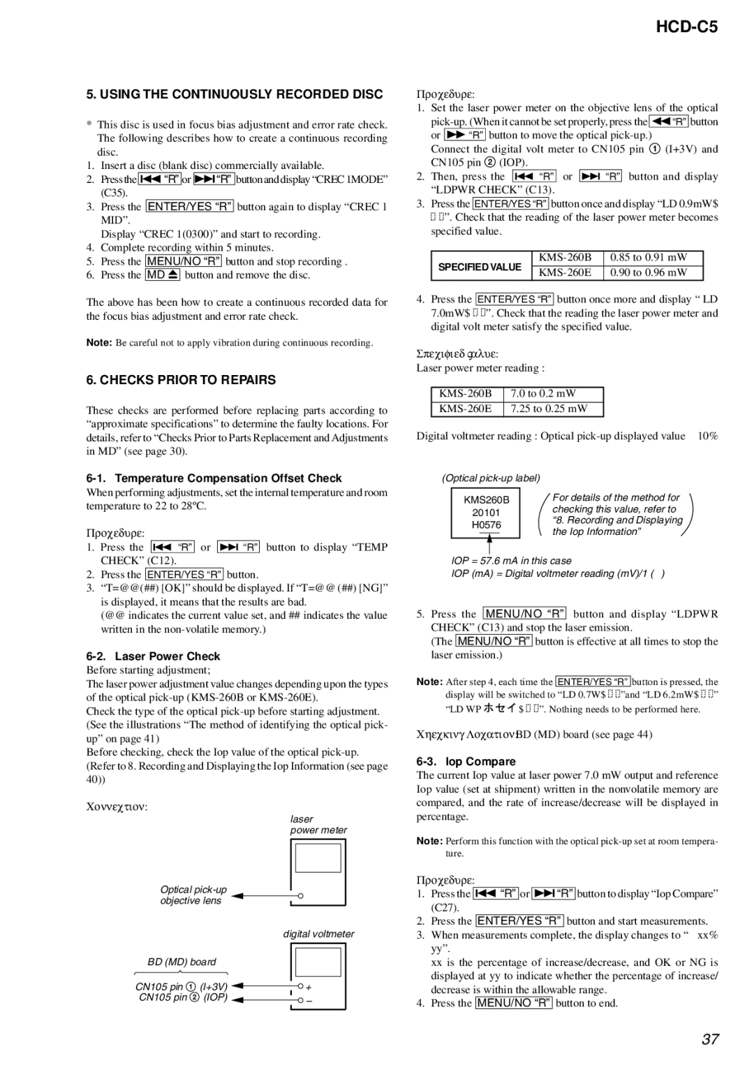
Connection:
laser
power meter
Optical
digital voltmeter
BD (MD) board |
|
|
|
|
|
|
|
|
|
| |
CN105 pin 1 (I+3V) |
|
|
|
|
|
|
|
| + |
| |
|
|
| |||
CN105 pin 2 (IOP) |
|
|
| – | |
|
|
| |||
|
|
|
| ||
|
|
|
|
|
|
HCD-C5
Procedure:
1.Set the laser power meter on the objective lens of the optical
Connect the digital volt meter to CN105 pin 1 (I+3V) and CN105 pin 2 (IOP).
2.Then, press the . “R” or > “R” button and display “LDPWR CHECK” (C13).
3. Press the ENTER/YES “R” button once and display “LD 0.9mW$
![]()
![]()
![]()
![]() ”. Check that the reading of the laser power meter becomes specified value.
”. Check that the reading of the laser power meter becomes specified value.
SPECIFIED VALUE | 0.85 to 0.91 mW | ||
0.90 to 0.96 mW | |||
|
4.Press the ENTER/YES “R” button once more and display “ LD 7.0mW$ ![]()
![]() ”. Check that the reading the laser power meter and digital volt meter satisfy the specified value.
”. Check that the reading the laser power meter and digital volt meter satisfy the specified value.
Specified Value:
Laser power meter reading :
Digital voltmeter reading : Optical
(Optical |
| ||||
|
|
|
| For details of the method for | |
| KMS260B |
| |||
| 20101 |
| checking this value, refer to | ||
|
| “8. Recording and Displaying | |||
| H0576 |
| |||
|
| the Iop Information” | |||
|
|
|
|
| |
|
|
|
|
| |
lOP = 57.6 mA in this case
lOP (mA) = Digital voltmeter reading (mV)/1 (Ω )
5.Press the MENU/NO “R” button and display “LDPWR CHECK” (C13) and stop the laser emission.
(The MENU/NO “R” button is effective at all times to stop the laser emission.)
Note: After step 4, each time the ENTER/YES “R” button is pressed, the display will be switched to “LD 0.7W$ ![]()
![]() ”and “LD 6.2mW$
”and “LD 6.2mW$ ![]()
![]() ”
”
“LD WP ![]()
![]()
![]()
![]() $
$ ![]()
![]()
![]()
![]() ”. Nothing needs to be performed here.
”. Nothing needs to be performed here.
Checking Location: BD (MD) board (see page 44)
6-3. Iop Compare
The current Iop value at laser power 7.0 mW output and reference Iop value (set at shipment) written in the nonvolatile memory are compared, and the rate of increase/decrease will be displayed in percentage.
Note: Perform this function with the optical
Procedure:
1.Press the .“R” or >“R” button to display “Iop Compare” (C27).
2.Press the ENTER/YES “R” button and start measurements.
3.When measurements complete, the display changes to “± xx% yy”.
xx is the percentage of increase/decrease, and OK or NG is displayed at yy to indicate whether the percentage of increase/ decrease is within the allowable range.
4.Press the MENU/NO “R” button to end.
37