14

1

RACCORD – PLOMBERIE BRUTE

Fermer les conduits d’alimentation en eau chaude et en eau froide avant de commencer.

IMPORTANT : NE PAS RETIRER LES PROTÈGE-ENDUIT (2) AVANT L’ÉTAPE 2.


Préparer les conduits d’alimentation en eau selon les dimensions de la plomberie brute.

Installer la VALVE (1) à la hauteur et à la profondeur indiquées. S’assurer que l’orifice de sortie portant la mention " SHR " pointe vers le haut.

Brancher le conduit d’alimentation en eau chaude (HOT) (6) à la soupape d’entrée de GAUCHE et le conduit d’alimentation en eau froide (COLD) (7) à la soupape d’entrée de DROITE.

Fixer solidement le CORPS D’APPAREIL DE PLOMBERIE (1) à l’entretoise de la structure murale.

Préparer la COLONNE MONTANTE (4) et le COUDE (3) pour la DOUCHE. Connecter à l’orifice de sortie HAUT portant la mention " SHR " du CORPS D’APPAREIL DE PLOMBERIE (1).

Préparer le TUYAU DE REMPLISSAGE DU BAIN (8), le COUDE (10) et le MAMELON (9) – PLOMBERIE BRUTE. Connecter à l’orifice de sortie BAS du CORPS D’APPAREIL DE PLOMBERIE (1).

Ajouter des entretoises à la structure murale et fixer la COLONNE MONTANTE DE LA DOUCHE (4) ainsi que LE TUYAU DE REMPLISSAGE DU BAIN (8).

Coiffer (11) le MAMELON (9) et BOUCHER (5) le COUDE (3); les valves doivent être fermées. Ouvrir les conduits d’alimentation en eau et vérifier s’il y a des fuites. Ouvrir les deux VALVES et vérifier s’il y a des fuites.

Fermer les valves et couper l’alimentation en eau. Terminer l’aménagement du mur.

2 FINISHING INSTALLATION

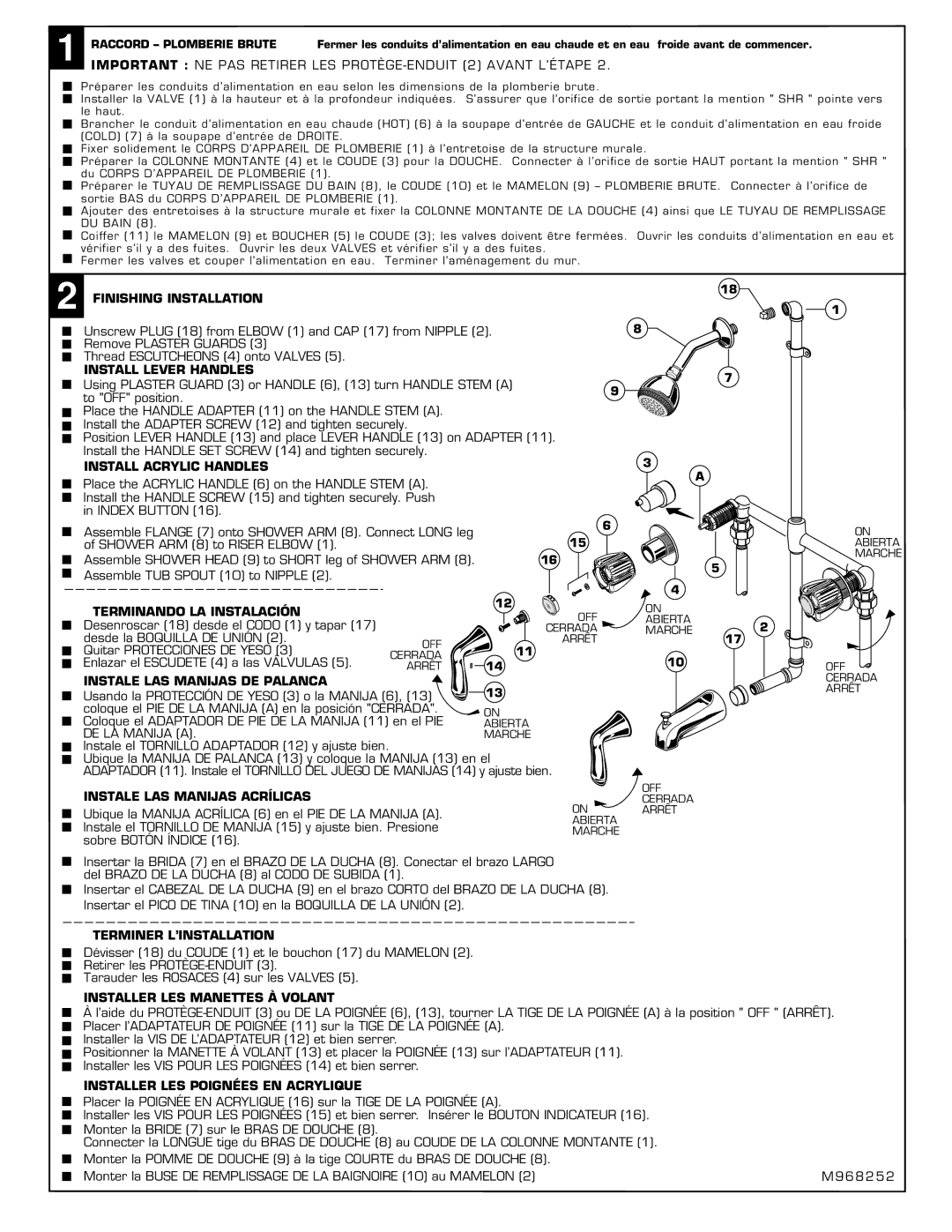
Unscrew PLUG (18) from ELBOW (1) and CAP (17) from NIPPLE (2).


Remove PLASTER GUARDS (3)


Thread ESCUTCHEONS (4) onto VALVES (5).


INSTALL LEVER HANDLES


Using PLASTER GUARD (3) or HANDLE (6), (13) turn HANDLE STEM (A)

9

to "OFF" position.


Place the HANDLE ADAPTER (11) on the HANDLE STEM (A).


Install the ADAPTER SCREW (12) and tighten securely.


Position LEVER HANDLE (13) and place LEVER HANDLE (13) on ADAPTER (11).


Install the HANDLE SET SCREW (14) and tighten securely.


INSTALL ACRYLIC HANDLES


18

8

7

3

1

Place the ACRYLIC HANDLE (6) on the HANDLE STEM (A). Install the HANDLE SCREW (15) and tighten securely. Push in INDEX BUTTON (16).

Assemble FLANGE (7) onto SHOWER ARM (8). Connect LONG leg of SHOWER ARM (8) to RISER ELBOW (1).

Assemble SHOWER HEAD (9) to SHORT leg of SHOWER ARM (8). Assemble TUB SPOUT (10) to NIPPLE (2).

TERMINANDO LA INSTALACIÓN

Desenroscar (18) desde el CODO (1) y tapar (17)


desde la BOQUILLA DE UNIÓN (2).

OFF

Quitar PROTECCIONES DE YESO (3)

CERRADA

Enlazar el ESCUDETE (4) a las VÁLVULAS (5).

ARRÊT

INSTALE LAS MANIJAS DE PALANCA


12

11

6

15

16

H

OFF CERRADA

ARRÊT

A

MAXW

A

L

L

M I N 1 - 5/8"

DEEP

5

4

ON ABIERTA

MARCHE2

17

10

ON

ABIERTA

MARCHE

OFF

CERRADA

Usando la PROTECCIÓN DE YESO (3) o la MANIJA (6), (13)

13

coloque el PIE DE LA MANIJA (A) en la posición "CERRADA".

ON

Coloque el ADAPTADOR DE PIE DE LA MANIJA (11) en el PIE

ABIERTA

DE LA MANIJA (A).

MARCHE

Instale el TORNILLO ADAPTADOR (12) y ajuste bien.


Ubique la MANIJA DE PALANCA (13) y coloque la MANIJA (13) en el

ADAPTADOR (11). Instale el TORNILLO DEL JUEGO DE MANIJAS (14) y ajuste bien.

INSTALE LAS MANIJAS ACRÍLICAS

ON

Ubique la MANIJA ACRÍLICA (6) en el PIE DE LA MANIJA (A).

ABIERTA

Instale el TORNILLO DE MANIJA (15) y ajuste bien. Presione

MARCHE

sobre BOTÓN ÍNDICE (16).

Insertar la BRIDA (7) en el BRAZO DE LA DUCHA (8). Conectar el brazo LARGO del BRAZO DE LA DUCHA (8) al CODO DE SUBIDA (1).

Insertar el CABEZAL DE LA DUCHA (9) en el brazo CORTO del BRAZO DE LA DUCHA (8). Insertar el PICO DE TINA (10) en la BOQUILLA DE LA UNIÓN (2).

OFF CERRADA ARRÊT

ARRÊT

TERMINER L’INSTALLATION

Dévisser (18) du COUDE (1) et le bouchon (17) du MAMELON (2).

Retirer les PROTÈGE-ENDUIT (3).

Tarauder les ROSACES (4) sur les VALVES (5).

INSTALLER LES MANETTES À VOLANT

Àl’aide du PROTÈGE-ENDUIT (3) ou DE LA POIGNÉE (6), (13), tourner LA TIGE DE LA POIGNÉE (A) à la position " OFF " (ARRÊT). Placer l’ADAPTATEUR DE POIGNÉE (11) sur la TIGE DE LA POIGNÉE (A).

Installer la VIS DE L’ADAPTATEUR (12) et bien serrer.

Positionner la MANETTE À VOLANT (13) et placer la POIGNÉE (13) sur l’ADAPTATEUR (11). Installer les VIS POUR LES POIGNÉES (14) et bien serrer.

INSTALLER LES POIGNÉES EN ACRYLIQUE


Placer la POIGNÉE EN ACRYLIQUE (16) sur la TIGE DE LA POIGNÉE (A).


Installer les VIS POUR LES POIGNÉES (15) et bien serrer. Insérer le BOUTON INDICATEUR (16).


Monter la BRIDE (7) sur le BRAS DE DOUCHE (8).


Connecter la LONGUE tige du BRAS DE DOUCHE (8) au COUDE DE LA COLONNE MONTANTE (1).


Monter la POMME DE DOUCHE (9) à la tige COURTE du BRAS DE DOUCHE (8).


Monter la BUSE DE REMPLISSAGE DE LA BAIGNOIRE (10) au MAMELON (2)

M968252

Page 2
Image 2
American Standard 3275 SERIES Finishing Installation, Install Lever Handles, Install Acrylic Handles

3275 SERIES specifications

The American Standard 3275 Series represents a significant step forward in the world of bathroom fixtures, combining thoughtful design with advanced technology for optimal user experience. Renowned for their durability and efficiency, the 3275 Series is particularly popular among homeowners and remodelers looking for high-quality, stylish options for their bathrooms.

One of the standout features of the 3275 Series is its innovative design, which emphasizes both aesthetics and functionality. The sleek lines and modern contours not only enhance the visual appeal of any bathroom but also ensure that each piece fits seamlessly into various design themes, from contemporary to traditional. The range includes a variety of sink models, toilet options, and bathtub choices, allowing homeowners to create a cohesive look throughout their bathrooms.

In terms of water efficiency, the 3275 Series shines with its Eco-friendly technology. Many models are equipped with WaterSense certification, which means they use significantly less water without compromising performance. This is an essential feature for environmentally conscious consumers who want to reduce their water consumption while still enjoying the luxury of a beautifully designed bathroom.

Furthermore, the 3275 Series incorporates advanced flushing systems that enhance performance and prevent clogs, a common issue in traditional toilets. With features like the powerful siphon jet action, users can expect a clean and efficient flush every time, thus minimizing the need for frequent maintenance. The toilets in this series are also designed for easy installation, making them favorable for DIY enthusiasts.

Another key characteristic of the American Standard 3275 Series is its commitment to comfort. Many models feature ergonomic designs that provide a more comfortable experience, whether sitting on the toilet or using the sink. The addition of soft-close lids in toilets prevents slamming, contributing to a quieter bathroom environment.

Lastly, the 3275 Series is built with quality materials that resist scratching, chipping, and fading, ensuring long-lasting beauty and performance. With a warranty that reflects the brand's confidence in their product, consumers can trust that they are making a wise investment in their home.

In summary, the American Standard 3275 Series is a blend of modern design, water-saving technology, and user comfort. Whether renovating a bathroom or building a new one, this series offers a range of options that cater to both style and functionality, making it a top choice for consumers.