
4251, M968412A specifications
The American Standard 4251, M968412A is a high-performing faucet that exemplifies modern design combined with innovative functionality. This faucet is notable for its elegant aesthetic, making it suitable for various kitchen and bathroom styles. The design features a sleek, streamlined profile that not only enhances visual appeal but also optimizes performance.One of the main features of the American Standard 4251 is its robust construction. Crafted from high-quality materials, this faucet is designed to withstand daily wear and tear while maintaining its pristine appearance. The finish options typically include polished chrome, brushed nickel, and oil-rubbed bronze, providing versatility to match different decor styles.
The M968412A incorporates advanced technologies such as the "EASY PAUSE" feature that allows users to pause the water flow temporarily, making it easier to complete tasks without water splashing everywhere. This thoughtful functionality significantly improves user experience in high-traffic areas.
Another standout characteristic is the faucet’s water efficiency. The American Standard 4251 is designed to minimize water consumption without sacrificing performance. It complies with EPA WaterSense criteria, which means it provides a flow rate that conserves water while still delivering a powerful spray. This eco-friendly aspect not only benefits users but also contributes to water conservation efforts.
Additionally, the American Standard 4251 is equipped with a ceramic disc valve. This state-of-the-art valve technology ensures a drip-free performance and prolongs the lifespan of the faucet. The smooth operation of the handle enhances usability, allowing for easy control over water temperature and flow.
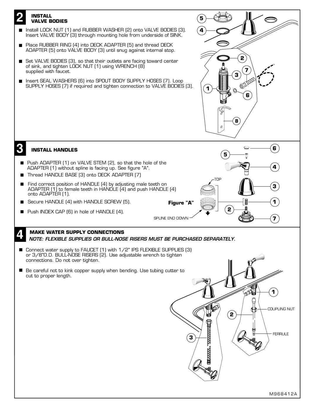
Installation is straightforward as well, thanks to the included mounting hardware and clear instructions. Compatibility with standard plumbing systems makes it an accessible choice for many homeowners.
Overall, the American Standard 4251, M968412A is a superior faucet that combines elegance, durability, and functionality. Its innovative features cater to the needs of modern users while maintaining a commitment to water conservation and ease of use. This faucet is an outstanding choice for anyone looking to upgrade their kitchen or bathroom with a blend of style and efficiency.