2 INSTALL HANDLES
2
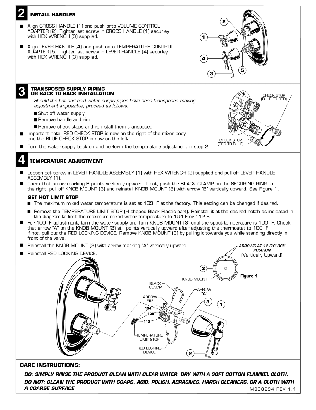
Align CROSS HANDLE (1) and push onto VOLUME CONTROL ADAPTER (2). Tighten set screw in CROSS HANDLE (1) securley with HEX WRENCH (3) supplied.
Align LEVER HANDLE (4) and push onto TEMPERATURE CONTROL ADAPTER (5). Tighten set screw in LEVER HANDLE (4) securley with HEX WRENCH (3) supplied.
1
4
3
5
3 TRANSPOSED SUPPLY PIPING OR BACK TO BACK INSTALLATION
Should the hot and cold water supply pipes have been transposed making adjustment impossible, proceed as follows:
![]()
![]() Shut off water supply.
Shut off water supply.
![]()
![]() Remove handle and rim
Remove handle and rim
![]() Remove check stops and
Remove check stops and
Important note: RED CHECK STOP is now on the right of the mixer body and the BLUE CHECK STOP is now on the left.
Turn the water supply back on and perform the temperature adjustment in step 2.
CHECK STOP
(RED TO BLUE)
CHECK STOP
(BLUE TO RED)
4 TEMPERATURE ADJUSTMENT
Loosen set screw in LEVER HANDLE ASSEMBLY (1) with HEX WRENCH (2) supplied and pull off LEVER HANDLE ASSEMBLY (1).
Check that arrow marking B points vertically upward. If not, push the BLACK CLAMP on the SECURING RING to the right, pull off KNOB MOUNT (3) and reinstall KNOB MOUNT (3) with arrow "B" vertically upward. See Figure 1.
SET HOT LIMIT STOP
The maximum mixed water temperature is set at 109 F at the factory. This setting can be changed if desired.
Remove the TEMPERATURE LIMIT STOP (H shaped Black Plastic part). Reinstall it at the desired notch as indicated in the diagram to limit the maximum mixed water temperature to 104 F or 112 F.
For 100 F adjustment, turn the water supply on. Turn KNOB MOUNT (3) until the spout temperature is 100 F. Check that arrow "A" on the KNOB MOUNT (3) still points vertically upward after adjusting the thermostat to 100 F.
If not, pull out the RED LOCKING DEVICE. Remove KNOB MOUNT (3) by pulling it towards you while standing directly in front of the valve.
Reinstall the KNOB MOUNT (3) with arrow marking "A" vertically upward. |
| ARROWS AT 12 O'CLOCK |
Reinstall RED LOCKING DEVICE. |
| POSITION |
| (Vertically Upward) | |
|
| |
| 3 |
|
KNOB MOUNT | Figure 1 | |
| ||
BLACK |
|
|
CLAMP | ARROW |
|
|
| |
ARROW | "A" |
|
|
| |
"B" | 3 | 1 |
104 |
| |
|
| |
109 |
|
|
112 |
|
|
TEMPERATURE |
|
|
LIMIT STOP |
|
|
RED LOCKING |
|
|
DEVICE | 2 |
|
CARE INSTRUCTIONS:
DO: SIMPLY RINSE THE PRODUCT CLEAN WITH CLEAR WATER. DRY WITH A SOFT COTTON FLANNEL CLOTH.
DO NOT: CLEAN THE PRODUCT WITH SOAPS, ACID, POLISH, ABRASIVES, HARSH CLEANERS, OR A CLOTH WITH A COARSE SURFACE