Replacing the Flame Sense/Hot Surface igniter Assembly
1.Remove the manifold/burner assembly. See Removing the Manifold/Burner Assembly.
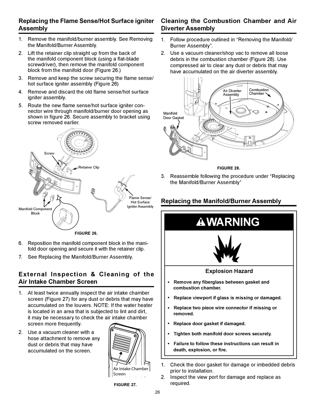
2.Lift the retainer clip straight up from the back of the manifold component block (using a
3.Remove and keep the screw securing the flame sense/ hot surface igniter assembly (Figure 26)
4.Remove and discard the old flame sense/hot surface igniter assembly.
5.Route the new flame sense/hot surface igniter con- nector wire through manifold/burner door opening as shown in figure 26. Secure assembly to bracket using screw removed earlier.
Screw
![]() Retainer Clip
Retainer Clip
Cleaning the Combustion Chamber and Air Diverter Assembly
1.Follow procedure outlined in “Removing the Manifold/ Burner Assembly”.
2.Use a vacuum cleaner/shop vac to remove all loose debris in the combustion chamber (Figure 28). Use compressed air to clear any dust or debris that may have accumulated on the air diverter assembly.
Air Diverter | Combustion |
Assembly | Chamber |
Manifold
Door Gasket
FIGURE 28.
3.Reassemble following the procedure under “Replacing the Manifold/Burner Assembly”
Manifold Component
Block
Flame Sense/
Hot Surface
Igniter Assembly
Replacing the Manifold/Burner Assembly
![]() WARNING
WARNING
FIGURE 26.
6.Reposition the manifold component block in the mani- fold door opening and secure it with the retainer clip.
7.See Replacing the Manifold/Burner Assembly.
External Inspection & Cleaning of the Air Intake Chamber Screen
1.At least twice annually inspect the air intake chamber screen (Figure 27) for any dust or debris that may have accumulated on the louvers. NOTE: If the water heater is located in an area that is subjected to lint and dirt,
it may be necessary to check the air intake chamber
screen more frequently.
2. Use a vacuum cleaner with a hose attachment to remove any dust or debris that may have accumulated on the screen.
Air Intake Chamb![]() er
er![]()
![]()
![]()
![]()
Screen
FIGURE 27.
Explosion Hazard
•Remove any fiberglass between gasket and combustion chamber.
•Replace viewport if glass is missing or damaged.
•Replace two piece wire connector if missing or removed.
•Replace door gasket if damaged.
•Tighten both manifold door screws securely.
•Failure to follow these instructions can result in death, explosion, or fire.
1.Check the door gasket for damage or imbedded debris prior to installation.
2.Inspect the view port for damage and replace as required.
26
