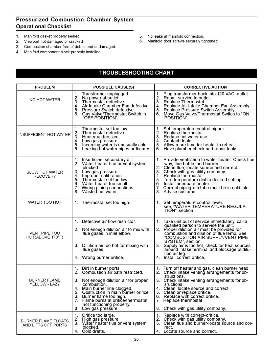
Pressurized Combustion Chamber System Operational Checklist
1.Manifold gasket properly sealed.
2.Viewport not damaged or cracked.
3.Combustion chamber free of debris and undamaged.
4.Manifold component block properly installed.
5.No leaks at manifold connection.
6.Manifold door screws securely tightened.
TROUBLESHOOTING CHART
PROBLEM | POSSIBLE CAUSE(S) | CORRECTIVE ACTION |
| 1. | Transformer unplugged. | 1. Plug transformer back into 120 VAC. outlet. | ||
NO HOT WATER | 2. | No power at outlet. | 2. | Repair service to outlet. | |
3. | Thermostat defective. | 3. | Replace Thermostat. | ||
| |||||
| 4. | Air Intake Chamber Fan defective. | 4. | Replace Air Intake Chamber Fan Assembly. | |
| 5. | Pressure Switch defective. | 5. | Replace Pressure Switch Assembly. | |
| 6. | Gas Valve/Thermostat Switch in | 6. | Move Gas Valve/Thermostat Switch to “ON | |
|
| “OFF POSITION”. |
| POSITION”. | |
|
|
| |||
| 1. Thermostat set too low. | 1. Set temperature control higher. | |||
INSUFFICIENT HOT WATER | 2. | Thermostat defective. | 2. | Replace thermostat. | |
| 3. | Heater undersized. | 3. | Reduce hot water use. | |
| 4. | Low gas pressure. | 4. | Contact dealer. | |
| 5. | Incoming water is unusually cold. | 5. | Allow more time for heater to reheat. | |
| 6. | Leaking hot water pipes or fixtures. | 6. | Have plumber check and repair leaks. | |
|
|
|
|
| |
| 1. | Insufficient secondary air. | 1. | Provide ventilation to water heater. Check flue | |
| 2. | Water heater flue or vent system | 2. | way, flue baffle, and burner. | |
| 3. | blocked. | Clean flue, locate source and correct. | ||
SLOW HOT WATER | Low gas pressure. | 3. | Check with gas utility company. | ||
RECOVERY | 4. | Improper calibration. | 4. | Replace thermostat. | |
| 5. | Thermostat set too low. | 5. | Turn temperature dial to desired setting. | |
| 6. | Water heater too small. | 6. | Install adequate heater. | |
| 7. | Wrong piping connections. | 7. Correct | ||
| 8. | Wasted hot water. | 8. | Advise customer. | |
|
|
|
|
| |
WATER TOO HOT | 1. | Thermostat set too high. | 1. | Set temperature control lower. | |
|
|
|
| see, “WATER TEMPERATURE REGULA- | |
|
|
|
| TION”, section. | |
|
|
|
|
| |
| 1. | Defective air flow restrictor. | 1. | Take unit out of service immediately, call a | |
| 2. | Not enough dilution air to mix with | 2. | qualified person to service the unit. | |
VENT PIPE TOO | Proper dilution air must be provided for | ||||
| flue gases in inlet elbow. |
| combustion and dilution of flue temp. See | ||
HOT(ABOVE 170°F) |
|
|
| “COMBUSTION AIR SUPPLY/VENT PIPE | |
| 3. | Dilution air too hot for mixing with | 3. | SYSTEM”, section. | |
| Supply air is too hot, check for heat sources | ||||
|
| flue gases. |
| around intake terminal and blockage of dilu- | |
| 4. | Wrong burner orifice. | 4. | tion air leg. | |
| Install correct orifice. | ||||
|
|
| |||
| 1. Dirt in burner ports. | 1. Turn off heater and gas, clean burner head. | |||
| 2. | Combustion air path restricted. | 2. | Check intake venting arrangements for ob- | |
BURNER FLAME | 3. | Not enough dilution air for proper | 3. | structions. | |
Check intake venting arrangements for ob- | |||||
YELLOW - LAZY | 4. | combustion. | 4. | sructions. | |
| Main burner line clogged. | Clean, locate source and correct. | |||
| 5. | Obstruction in main burner orifice. | 5. | Clean or replace orifice. | |
| 6. | Burner flame too high. | 6. | Replace with correct orifice. | |
| 7. Flame burns at orifice/thermostat | 7. | Replace thermostat | ||
| 8. | not functioning properly. | 8. | Check with gas utility company. | |
| Low gas pressure. | ||||
| 1. | Orifice too large. | 1. | Replace with | |
BURNER FLAME FLOATS | 2. | High gas pressure. | 2. | Check with gas utility company. | |
3. | Water heater flue or vent system | 3. | Clean flue and | ||
AND LIFTS OFF PORTS | |||||
| blocked. |
| rect. | ||
| 4. | 4. | |||
| Cold drafts. | Locate source and correct. | |||
28
