10. GRAPHIC EQ: These sliders control the output frequencies indicated above each con- trol. The center position of each control is flat (no boost or cut).
11. MASTER: Set the overall output level of the amplifier with this control. Pulling this knob out actives the Graphic EQ (#10). When a footswitch is connected (#24, rear panel) this switch is disabled.
12. BALANCE (B3158 only): This control proportions the output signal between the low and high frequency output jacks (see #18, rear panel) when using the amp in the biamp mode.
13. LIMIT LED(S): The LED illuminates whenever the amplifier is near full output, indicating that the internal limiter is keeping the output from distorting.
B3/B328/B3158 Bass Amplifier
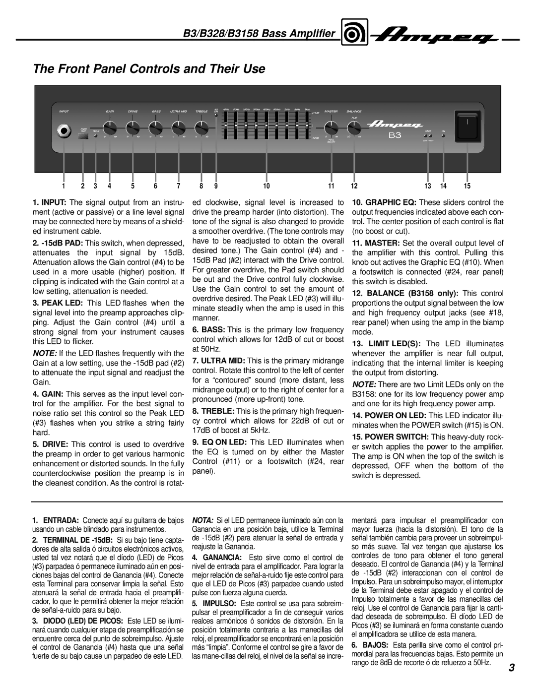
The Front Panel Controls and Their Use
INPUT | | | GAIN | DRIVE | BASS | ULTRA MID | TREBLE | EQ | 40Hz | 80Hz | 150Hz | 300Hz | 600Hz | 900Hz | 2kHz | 5kHz | 8kHz | BALANCE | | |
| | ON | | | | | | | | | MASTER | | |
| | | | | | | | | | | | | | | | | +12dB | | | | |
| | | | | | | | | | | | | | | | | | FLAT | | | |
| | | | | | | | | | | | | | | | | 0 | | | | |
| -15dB | | | | | | | | | | | | | | | | | | LIMIT | ON | |
| PAD | PEAK | | | | | | | | | | | | | | | | | |
| | | | | | | | | | | | | | | | | -12dB | LO | HI | | |
| | | | | | | | | | | | | | | | | PULL | | LOW HIGH | | |
| | | | | | | | | | | | | | | | | EQ ON | | | |
| | | | | | | | | | | | | | | | | | | | |
1 | 2 | 3 | 4 | 5 | 6 | 7 | 8 | 9 | | | | | 10 | | | | 11 | 12 | 13 | 14 | 15 |
1.INPUT: The signal output from an instru- ment (active or passive) or a line level signal may be connected here by means of a shield- ed instrument cable.
2.-15dB PAD: This switch, when depressed, attenuates the input signal by 15dB. Attenuation allows the Gain control (#4) to be used in a more usable (higher) position. If clipping is indicated with the Gain control at a low setting, attenuation is needed.
3.PEAK LED: This LED flashes when the signal level into the preamp approaches clip- ping. Adjust the Gain control (#4) until a strong signal from your instrument causes this LED to flicker.
NOTE: If the LED flashes frequently with the Gain at a low setting, use the -15dB pad (#2) to attenuate the input signal and readjust the Gain.
ed clockwise, signal level is increased to drive the preamp harder (into distortion). The tone of the signal is also changed to provide a smoother overdrive. (The tone controls may have to be readjusted to obtain the overall desired tone.) The Gain control (#4) and - 15dB Pad (#2) interact with the Drive control. For greater overdrive, the Pad switch should be out and the Drive control fully clockwise. Use the Gain control to set the amount of overdrive desired. The Peak LED (#3) will illu- minate steadily when the amp is used in this manner.
6. BASS: This is the primary low frequency control which allows for 12dB of cut or boost at 50Hz.
7. ULTRA MID: This is the primary midrange control. Rotate this control to the left of center
for a “contoured” sound (more distant, less NOTE: There are two Limit LEDs only on the midrange output) or to the right of center for a
4. GAIN: This serves as the input level con- |
trol for the amplifier. For the best signal to |
pronounced (more up-front) tone.
B3158: one for its low frequency power amp and one for its high frequency power amp.
noise ratio set this control so the Peak LED |
(#3) flashes when you strike a string fairly |
hard. |
5. DRIVE: This control is used to overdrive |
the preamp in order to get various harmonic |
enhancement or distorted sounds. In the fully |
counterclockwise position the preamp is in |
the cleanest condition. As the control is rotat- |
| 8. TREBLE: This is the primary high frequen- | 14. POWER ON LED: This LED indicator illu- |
| cy control which allows for 22dB of cut or |
| minates when the POWER switch (#15) is ON. |
| 17dB of boost at 5kHz. |
| 15. POWER SWITCH: This heavy-duty rock- |
| 9. EQ ON LED: This LED illuminates when |
| er switch applies the power to the amplifier. |
| the EQ is turned on by either the Master |
| The amp is ON when the top of the switch is |
| Control (#11) or a footswitch (#24, rear |
| depressed, OFF when the bottom of the |
| panel). |
| switch is depressed. |
| |
1.ENTRADA: Conecte aquí su guitarra de bajos usando un cable blindado para instrumentos.
2.TERMINAL DE -15dB:Si su bajo tiene capta- dores de alta salida ó circuitos electrónicos activos, usted tal vez notará que el díodo (LED) de Picos (#3) parpadea ó permanece iluminado aún en posi- ciones bajas del control de Ganancia (#4). Conecte esta Terminal para conservar limpia la señal. Esto atenuará la señal de entrada hacia el preamplifi- cador, lo que le permitirá obtener la mejor relación de señal-a-ruido para su bajo.
3.DIODO (LED) DE PICOS: Este LED se ilumi- nará cuando cualquier etapa de preamplificación se encuentre cerca del punto de sobreimpulso. Ajuste el control de Ganancia (#4) hasta que una señal fuerte de su bajo cause un parpadeo de este LED.
NOTA: Si el LED permanece iluminado aún con la | mentará para impulsar el preamplificador con | |
Ganancia en una posición baja, utilice la Terminal | mayor fuerza (hacia la distorsión). El tono de la | |
de -15dB (#2) para atenuar la señal de entrada y | señal también cambia para proveer un sobreimpul- | |
reajuste la Ganancia. | so más suave. Tal vez tengan que ajustarse los | |
4. GANANCIA: Esto sirve como el control de | controles de tono para obtener el tono general | |
nivel de entrada para el amplificador. Para lograr la | deseado. El control de Ganancia (#4) y la Terminal | |
mejor relación de señal-a-ruido fije este control para | de -15dB (#2) interaccionan con el control de | |
que el LED de Picos (#3) parpadee cuando usted | Impulso. Para un sobreimpulso mayor, el interruptor | |
pulse con fuerza alguna cuerda. | de la Terminal debe estar apagado y el control de | |
5. IMPULSO: Este control se usa para sobreim- | Impulso totalmente a favor de las manecillas del | |
reloj. Use el control de Ganancia para fijar la canti- | |
pulsar el preamplificador a fin de conseguir varios | |
dad deseada de sobreimpulso. El díodo LED de | |
realces armónicos ó sonidos de distorsión. En la | |
Picos (#3) se iluminará en forma constante cuando | |
posición totalmente contraria a las manecillas del | |
el amplificadora se utilice de esta manera. | |
reloj, el preamplificador se encontrará en la posición | |
6. BAJOS: Esta perilla sirve como el control pri- | |
más “limpia”. Conforme el control se gire a favor de | |
las mane-cillas del reloj, el nivel de la señal se incre- | mordial para las frecuencias bajas. Esto permite un | |
| rango de 8dB de recorte ó de refuerzo a 50Hz. | 3 |
| |