Ampeg B3158, B328 manual Rear Panel, Ground Prong of the AC Plug

Models: B3158 B3 B328

1 8
Download 8 pages 22.39 Kb
Page 4
Image 4

B3/B328/B3158 Bass Amplifier

The Front Panel Controls and Their Use

7.ULTRA-MEDIANOS:Este es el control primor- dial para el rango de las frecuencias medianas. Gire el control del centro hacia la izquierda para lograr un sonido de contorno (más distante, menor salida en el rango mediano) ó del centro hacia la derecha para obtener un sonido realmente penetrante.

8.AGUDOS: Esta perilla sirve como el control pri- mordial para las frecuencias altas. Esto permite un rango de 17dB de refuerzo ó 22dB de recorte a 5kHz.

9.EQ EN LED: Este dÌodo LED indicador se ilu- mina cuando usted activa el EQ mediante el control Maestro (#14) del panel delantero ó el interruptor de pie (#24) del panel posterior.

10.EQ GRAFICO: Estos controles deslizantes (cursores) le permiten ajustar la salida de las fre- cuencias que se muestran junto a cada control. La posición central de cada control es plana (sin

refuerzo ni recorte). Estos controles sólo afectan el sonido cuando el EQ esé prendido.

11.MAESTRO: Fije mediante este control el nivel general de salida del amplificador. El Circuito de Efectos y la Salida Equilibrada (#19, 20, 23) no se verán afectadas por el control Maestro. Jalando el control Maestro se prende el EQ Gráfico (#10). Cuando se utiliza el interruptor de pie, se pasa por alto el interruptor del panel delantero.

12.EQUILIBRIO (SOLO EN EL B358): Este con- trol varía el nivel de la señal entre las salidas de bajas y altas frecuencias (véase el #18) para ade- cuar aún más el sonido).

13.DIODOS LED DE LIMITE: Este LED indicador parpadeará cada vez que se requiera el circuito lim- itador interno para conservar limpia la señal de sal- ida del amplificador. Esto indica que el amplificador está aproximándose a su salida máxima y que el

limitador está impidiendo el aplanamiento (“clip- ping”) de la señal de salida.

NOTA: Hay dos circuitos Limitadores dentro del

B3158: uno para su amplificador de potencia de frecuencias bajas y otro para su amplificador de potencia de frecuencias altas. Todos los demás modelos tienen un solo circuito Limitador, y por lo tanto un solo LED de Limite.

14.DIODO LED DE POTENCIA ENCENDIDA: Este LED indicador se ilumina cuando se prende el interruptor de Potencia (#15).

15.INTERRUPTOR DE POTENCIA: Este interrup- tor de servicio pesado tipo vaivén aplica la energía de CA al amplificador: el amplificador se PRENDE en la posición hacia arriba (“I”), y se APAGA en la posición hacia abajo

The Rear Panel

FOR 100-120VAC, 50/60Hz: T5A, 250V

FOR 220-240VAC, 50/60Hz: T2.5A, 250V

CAUTION

RISK OF ELECTRIC SHOCK

DO NOT OPEN

AVIS: RISQUE DE CHOC ELECTRIQUE

NE PAS OUVRIR

WARNING: TO REDUCE THE RISK OF FIRE OR ELECTRIC SHOCK, SO NO EXPOSE THIS EQUIP- MENT TO RAIN OR MOISTURE.

SPEAKERS

HIGH


LOW

50 WATTS

100 WATTS

@8 OHMS

@4 OHMS

8 OHM .

4

MIN.

MODEL B-3158

SERIAL #

500 WATTS MAX.

115VAC-60Hz

EFFECTS

LOOP

POST

PRE

-20dB

0dB

RETURN SEND

BAL. FOOT

OUT SWITCH

16

17

18

19

20

21 22

23

24

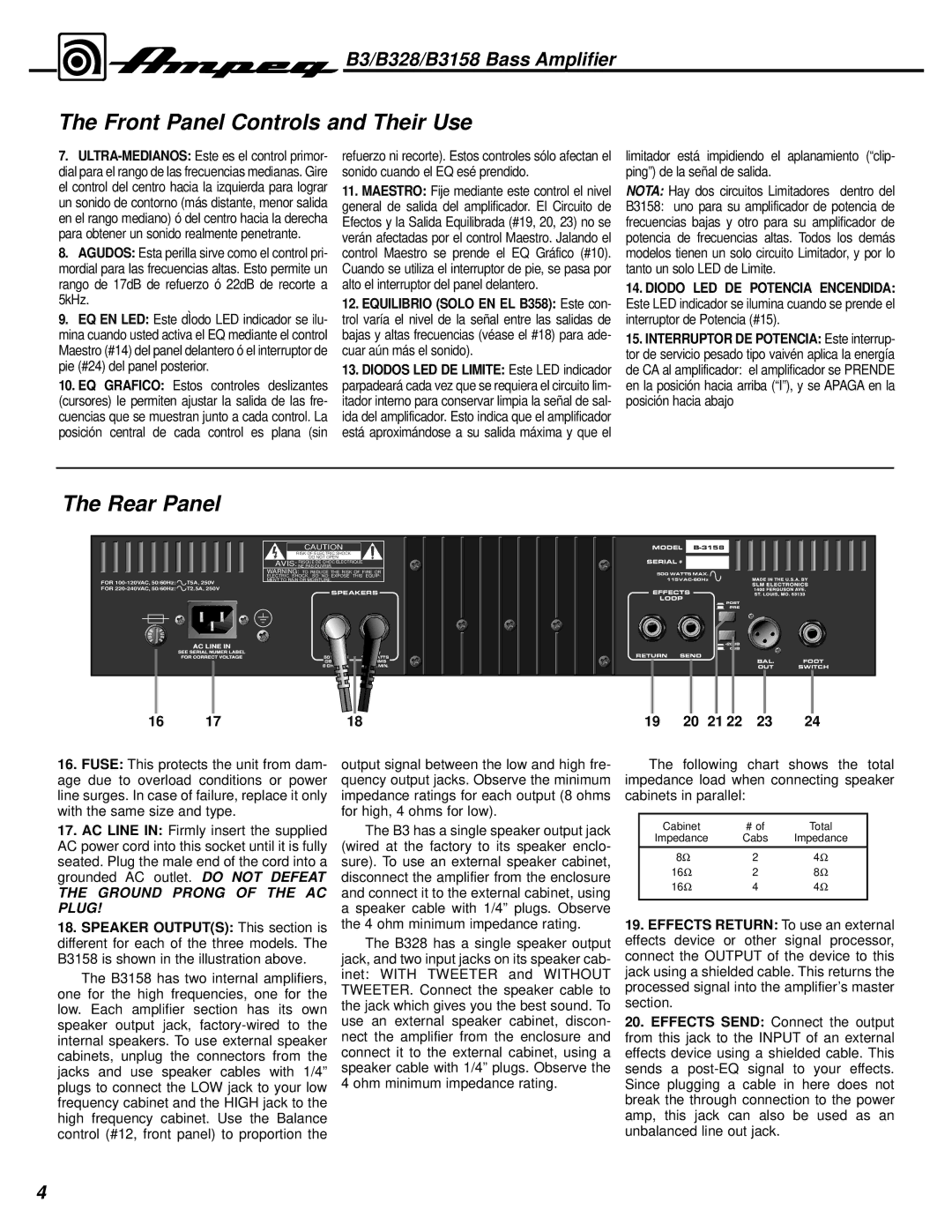
16.FUSE: This protects the unit from dam- age due to overload conditions or power line surges. In case of failure, replace it only with the same size and type.

17.AC LINE IN: Firmly insert the supplied AC power cord into this socket until it is fully seated. Plug the male end of the cord into a grounded AC outlet. DO NOT DEFEAT

THE GROUND PRONG OF THE AC PLUG!

18.SPEAKER OUTPUT(S): This section is different for each of the three models. The B3158 is shown in the illustration above.

The B3158 has two internal amplifiers, one for the high frequencies, one for the low. Each amplifier section has its own speaker output jack, factory-wired to the internal speakers. To use external speaker cabinets, unplug the connectors from the jacks and use speaker cables with 1/4” plugs to connect the LOW jack to your low frequency cabinet and the HIGH jack to the high frequency cabinet. Use the Balance control (#12, front panel) to proportion the

output signal between the low and high fre- quency output jacks. Observe the minimum impedance ratings for each output (8 ohms for high, 4 ohms for low).

The B3 has a single speaker output jack (wired at the factory to its speaker enclo- sure). To use an external speaker cabinet, disconnect the amplifier from the enclosure and connect it to the external cabinet, using a speaker cable with 1/4” plugs. Observe the 4 ohm minimum impedance rating.

The B328 has a single speaker output jack, and two input jacks on its speaker cab- inet: WITH TWEETER and WITHOUT TWEETER. Connect the speaker cable to the jack which gives you the best sound. To use an external speaker cabinet, discon- nect the amplifier from the enclosure and connect it to the external cabinet, using a speaker cable with 1/4” plugs. Observe the 4 ohm minimum impedance rating.

The following chart shows the total impedance load when connecting speaker cabinets in parallel:

Cabinet

# of

Total

Impedance

Cabs

Impedance


8

2

4

16

2

8

16

4

4


19.EFFECTS RETURN: To use an external effects device or other signal processor, connect the OUTPUT of the device to this jack using a shielded cable. This returns the processed signal into the amplifier’s master section.

20.EFFECTS SEND: Connect the output from this jack to the INPUT of an external effects device using a shielded cable. This sends a post-EQ signal to your effects. Since plugging a cable in here does not break the through connection to the power amp, this jack can also be used as an unbalanced line out jack.

4

Page 4
Image 4
Ampeg B3158, B328 manual Rear Panel, Ground Prong of the AC Plug