SVT-5 PRO Bass Amplifier
The Rear Panel
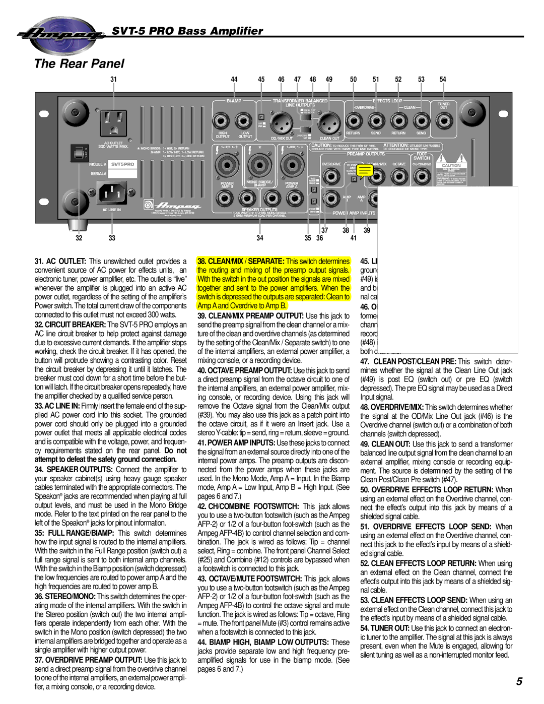
| 31 | 44 | 45 | 46 | 47 | 48 | 49 | 50 | 51 | 52 | 53 | 54 |
|
|
|
|
|
| CLEAN POST |
|
|
|
|
|
|
|
|
|
|
|
| CLEAN PRE |
|
|
|
|
|
|
|
|
|
|
| OVERDRIVE |
|
|
|
|
|
| |
|
|
|
|
|
| MIX |
|
|
|
|
|
|
|
| * |
|
|
|
|
|
|
|
|
|
|
| SVT5PRO |
|
|
|
|
|
|
|
|
|
|
|
|
|
|
|
|
|
| 37 | 38 | 39 | 40 |
|
|
32 | 33 |
| 34 |
|
| 35 | 36 | 41 |
|
| 42 | 43 |
31.AC OUTLET: This unswitched outlet provides a convenient source of AC power for effects units, an electronic tuner, power amplifier, etc. The outlet is “live” whenever the amplifier is plugged into an active AC power outlet, regardless of the setting of the amplifier’s Power switch. The total current draw of the components connected to this outlet must not exceed 300 watts.
32.CIRCUIT BREAKER: The
33.AC LINE IN: Firmly insert the female end of the sup- plied AC power cord into this socket. The grounded power cord should only be plugged into a grounded power outlet that meets all applicable electrical codes and is compatible with the voltage, power, and frequen- cy requirements stated on the rear panel. Do not attempt to defeat the safety ground connection.
34.SPEAKER OUTPUTS: Connect the amplifier to your speaker cabinet(s) using heavy gauge speaker cables terminated with the appropriate connectors. The Speakon® jacks are recommended when playing at full output levels, and must be used in the Mono Bridge mode. Refer to the text printed on the rear panel to the left of the Speakon® jacks for pinout information.
35: FULL RANGE/BIAMP: This switch determines how the input signal is routed to the internal amplifiers. With the switch in the Full Range position (switch out) a full range signal is sent to both internal amp channels. With the switch in the Biamp position (switch depressed) the low frequencies are routed to power amp A and the high frequencies are routed to power amp B.
36.STEREO/MONO: This switch determines the oper- ating mode of the internal amplifiers. With the switch in the Stereo position (switch out) the two internal ampli- fiers operate independently from each other. With the switch in the Mono position (switch depressed) the two internal amplifiers are bridged together and operate as a single amplifier with higher output power.
37.OVERDRIVE PREAMP OUTPUT: Use this jack to send a direct preamp signal from the overdrive channel to one of the internal amplifiers, an external power ampli- fier, a mixing console, or a recording device.
38.CLEAN/MIX / SEPARATE: This switch determines the routing and mixing of the preamp output signals. With the switch in the out position the signals are mixed together and sent to the power amplifiers. When the switch is depressed the outputs are separated: Clean to Amp A and Overdrive to Amp B.
39.CLEAN/MIX PREAMP OUTPUT: Use this jack to send the preamp signal from the clean channel or a mix- ture of the clean and overdrive channels (as determined by the setting of the Clean/Mix / Separate switch) to one of the internal amplifiers, an external power amplifier, a mixing console, or a recording device.
40.OCTAVE PREAMP OUTPUT: Use this jack to send a direct preamp signal from the octave circuit to one of the internal amplifiers, an external power amplifier, mix- ing console, or recording device. Using this jack will remove the Octave signal from the Clean/Mix output (#39). You may also use this jack as a patch point into the octave circuit, as if it were an Insert jack. Use a stereo
41.POWER AMP INPUTS: Use these jacks to connect the signal from an external source directly into one of the internal power amps. The preamp outputs are discon- nected from the power amps when these jacks are used. In the Mono Mode, Amp A = Input. In the Biamp mode, Amp A = Low Input, Amp B = High Input. (See pages 6 and 7.)
42.CH/COMBINE FOOTSWITCH: This jack allows you to use a
43.OCTAVE/MUTE FOOTSWITCH: This jack allows you to use a
44.BIAMP HIGH, BIAMP LOW OUTPUTS: These jacks provide separate low and high frequency pre- amplified signals for use in the biamp mode. (See pages 6 and 7.)
45.LIFT/GND: With this switch in the out position the ground pins of the Balanced Line Output jacks (#46, #49) is interrupted. This may help reduce residual hum and buzz which is sometimes picked up by line out sig- nal cables.
46.OD/MIX LINE OUT: Use this jack to send a trans- former balanced line output signal from the overdrive channel to an external amplifier, mixing console or recording equipment. When the Overdrive/Mix switch (#48) is depressed, this jack sends a line out signal from both channels.
47.CLEAN POST/CLEAN PRE: This switch deter- mines whether the signal at the Clean Line Out jack (#49) is post EQ (switch out) or pre EQ (switch depressed). The pre EQ signal may be used as a Direct Input signal.
48.OVERDRIVE/MIX: This switch determines whether the signal at the OD/Mix Line Out jack (#46) is the Overdrive channel (switch out) or a combination of both channels (switch depressed).
49.CLEAN OUT: Use this jack to send a transformer balanced line output signal from the clean channel to an external amplifier, mixing console or recording equip- ment. The source is determined by the setting of the Clean Post/Clean Pre switch (#47).
50.OVERDRIVE EFFECTS LOOP RETURN: When using an external effect on the Overdrive channel, con- nect the effect’s output into this jack by means of a shielded signal cable.
51.OVERDRIVE EFFECTS LOOP SEND: When using an external effect on the Overdrive channel, con- nect this jack to the effect’s input by means of a shield- ed signal cable.
52.CLEAN EFFECTS LOOP RETURN: When using an external effect on the Clean channel, connect the effect’s output into this jack by means of a shielded sig- nal cable.
53.CLEAN EFFECTS LOOP SEND: When using an external effect on the Clean channel, connect this jack to the effect’s input by means of a shielded signal cable.
54.TUNER OUT: Use this jack to connect an electron- ic tuner to the amplifier. The signal at this jack is always present, even when the Mute is engaged, allowing for silent tuning as well as a
5