EXTROL® L SERIES
REPLACEMENT BLADDER INSTRUCTIONS
Models 200-L through 15000-L
NOTE: Inspect for shipping damage and notify freight carrier or store where purchased immediately if damage is present. To avoid risk of personal injury and property damage, if the product appears to be malfunctioning or shows signs of corrosion, call a qualified professional immediately. Current copies of the Product manual can be viewed at www.amtrol.com. Use proper safety equipment when installing.
THIS IS THE SAFETY ALERT SYMBOL. IT IS USED TO ALERT YOU TO POTENTIAL PERSONAL INJURY AND OTHER HAZARDS. OBEY ALL SAFETY MESSAGES THAT FOLLOW THIS SYMBOL TO REDUCE THE RISK OF PERSONAL INJURY AS WELL AS PROPERTY DAMAGE.
READ CAREFULLY THE EXTROL ![]() REPLACEMENT BLADDER INSTRUCTIONS TO AVOID SERIOUS PERSONAL INJURY AND PROPERTY HAZARDS AND TO ENSURE SAFE USE AND PROPER CARE
REPLACEMENT BLADDER INSTRUCTIONS TO AVOID SERIOUS PERSONAL INJURY AND PROPERTY HAZARDS AND TO ENSURE SAFE USE AND PROPER CARE
OF THIS PRODUCT.
EXPLOSION OR RUPTURE HAZARD. THE ![]() EXPANSION TANK MUST BE OPERATED SO THAT THE PRESSURE DOES NOT EXCEED THE MAXIMUM
EXPANSION TANK MUST BE OPERATED SO THAT THE PRESSURE DOES NOT EXCEED THE MAXIMUM
WORKING PRESSURE.
This Product, like most Products under ![]() pressure, may over time corrode, weaken and burst or explode, causing serious or fatal injury, leaking or flooding and/or property damage. To minimize risk, a licensed professional must install and periodically inspect and service the Product. A drip pan connected to an adequate drain must be installed if leaking or flooding could cause property damage. Do not locate in an area where leaking could cause property damage to the area adjacent to
pressure, may over time corrode, weaken and burst or explode, causing serious or fatal injury, leaking or flooding and/or property damage. To minimize risk, a licensed professional must install and periodically inspect and service the Product. A drip pan connected to an adequate drain must be installed if leaking or flooding could cause property damage. Do not locate in an area where leaking could cause property damage to the area adjacent to
the appliance or to lower floors of the structure.
Installation
1.Isolate tank from system.
2.Release system pressure from tank.
3.Remove air valve core to bleed remaining air charge (Figure 1).
4.Remove drain plug (Figure 2).
5.Disconnect system connection.
6.Mark mating flanges in order to match when
7.Remove bolted upper flange and dip tube/hose.
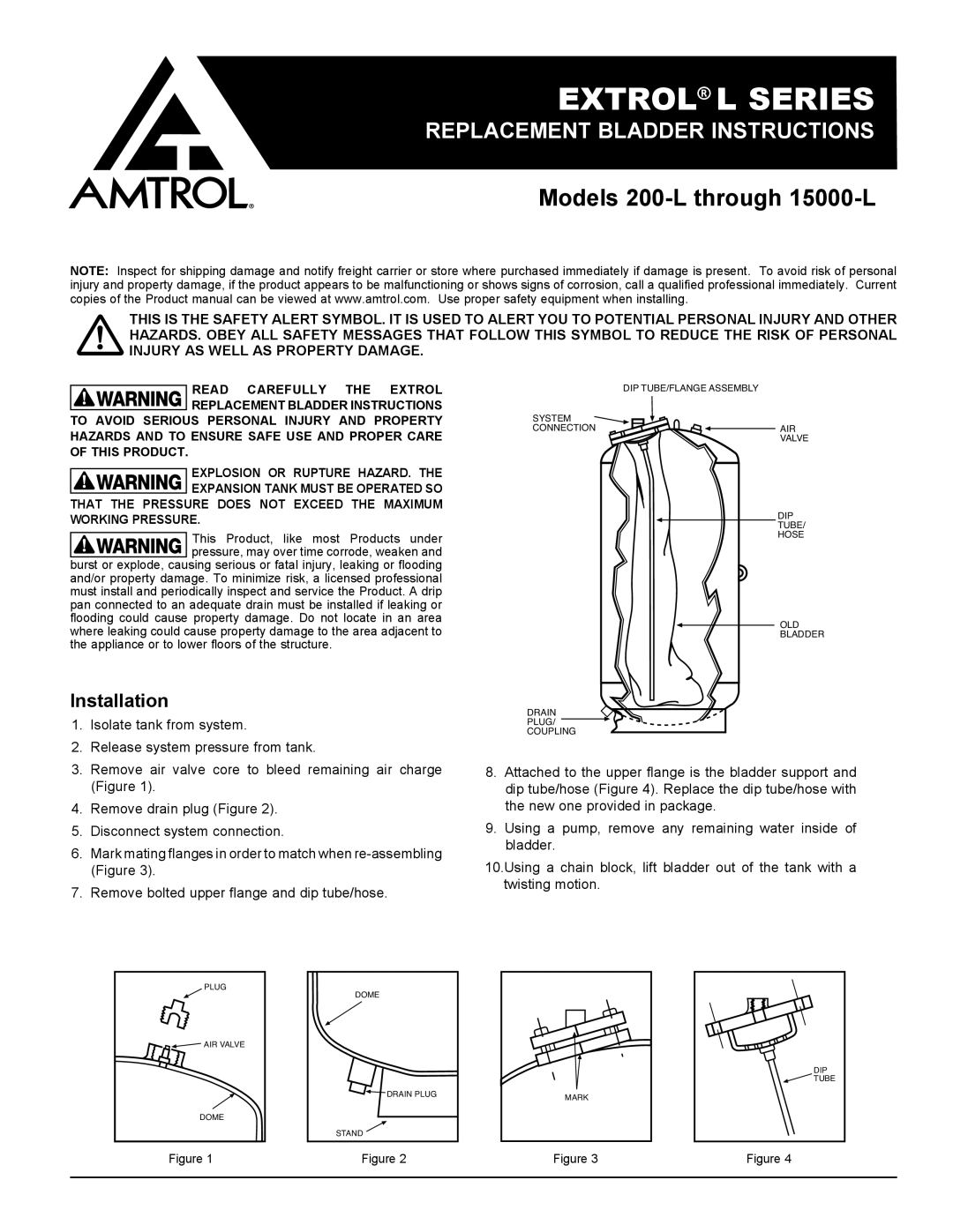
DIP TUBE/FLANGE ASSEMBLY
SYSTEM
CONNECTION![]() AIR
AIR
VALVE
DIP
TUBE/
HOSE
OLD
BLADDER
DRAIN
PLUG/
COUPLING
8.Attached to the upper flange is the bladder support and dip tube/hose (Figure 4). Replace the dip tube/hose with the new one provided in package.
9.Using a pump, remove any remaining water inside of bladder.
10.Using a chain block, lift bladder out of the tank with a twisting motion.
PLUG
![]() AIR VALVE
AIR VALVE
DOME
DOME
DRAIN PLUG | MARK |
|
STAND ![]()
DIP
![]() TUBE
TUBE
Figure 1 | Figure 2 | Figure 3 | Figure 4 |
|
|
|
|