11.Pump out water remaining in very bottom of tank.
12.Wash down inside walls of tank as necessary.
13.Mop up remaining water.
14.Dry out inside of tank (reversed vacuum cleaner or air line from a compressor).
15.Clean out any remaining dirt.
16.Examine interior for any rust blisters and remove them.
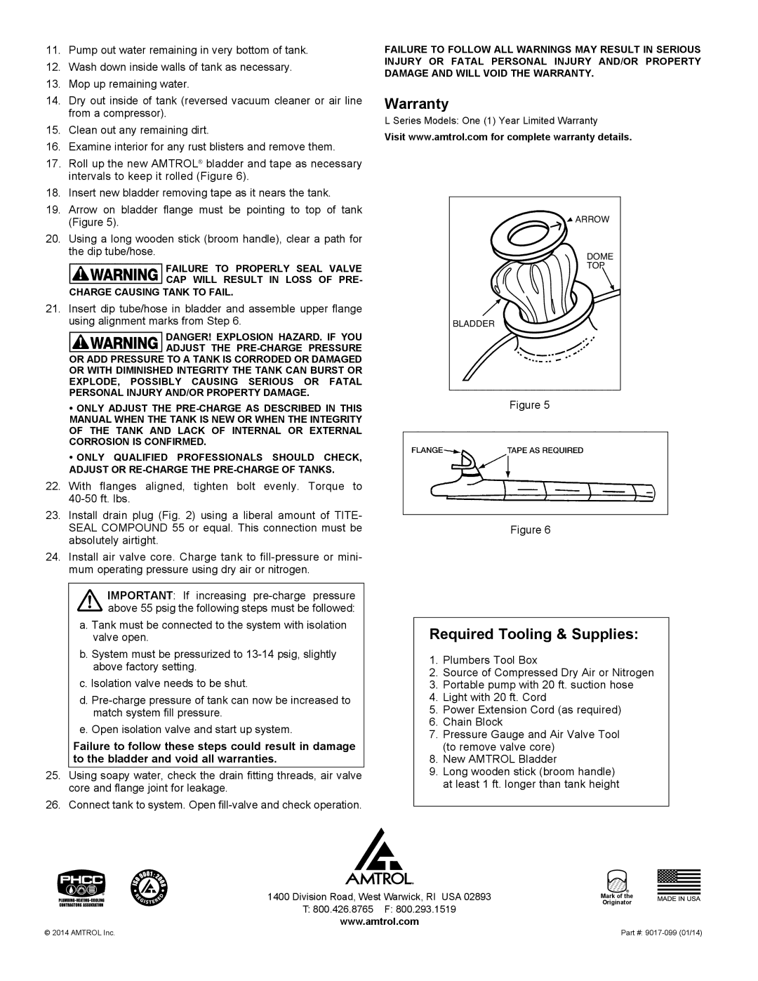
17.Roll up the new AMTROL® bladder and tape as necessary intervals to keep it rolled (Figure 6).
18.Insert new bladder removing tape as it nears the tank.
19.Arrow on bladder flange must be pointing to top of tank (Figure 5).
20.Using a long wooden stick (broom handle), clear a path for the dip tube/hose.
FAILURE TO PROPERLY SEAL VALVE
CAP WILL RESULT IN LOSS OF PRE- CHARGE CAUSING TANK TO FAIL.
21.Insert dip tube/hose in bladder and assemble upper flange using alignment marks from Step 6.
DANGER! EXPLOSION HAZARD. IF YOU
ADJUST THE
•ONLY ADJUST THE
MANUAL WHEN THE TANK IS NEW OR WHEN THE INTEGRITY OF THE TANK AND LACK OF INTERNAL OR EXTERNAL CORROSION IS CONFIRMED.
•ONLY QUALIFIED PROFESSIONALS SHOULD CHECK,
ADJUST OR
22.With flanges aligned, tighten bolt evenly. Torque to
23.Install drain plug (Fig. 2) using a liberal amount of TITE- SEAL COMPOUND 55 or equal. This connection must be absolutely airtight.
24.Install air valve core. Charge tank to
IMPORTANT: If increasing
a. Tank must be connected to the system with isolation valve open.
b. System must be pressurized to
c. Isolation valve needs to be shut.
d.
e. Open isolation valve and start up system.
Failure to follow these steps could result in damage to the bladder and void all warranties.
25.Using soapy water, check the drain fitting threads, air valve core and flange joint for leakage.
26.Connect tank to system. Open
FAILURE TO FOLLOW ALL WARNINGS MAY RESULT IN SERIOUS INJURY OR FATAL PERSONAL INJURY AND/OR PROPERTY DAMAGE AND WILL VOID THE WARRANTY.
Warranty
L Series Models: One (1) Year Limited Warranty
Visit www.amtrol.com for complete warranty details.
![]() ARROW
ARROW
DOME
TOP
BLADDER
Figure 5
Figure 6
Required Tooling & Supplies:
1.Plumbers Tool Box
2.Source of Compressed Dry Air or Nitrogen
3.Portable pump with 20 ft. suction hose
4.Light with 20 ft. Cord
5.Power Extension Cord (as required)
6.Chain Block
7.Pressure Gauge and Air Valve Tool (to remove valve core)
8.New AMTROL Bladder
9.Long wooden stick (broom handle) at least 1 ft. longer than tank height
1400 Division Road, West Warwick, RI USA 02893
T:800.426.8765 F: 800.293.1519 www.amtrol.com
Mark of the Originator
© 2014 AMTROL Inc. | Part #: |