AVS-SL-0201-824 specifications
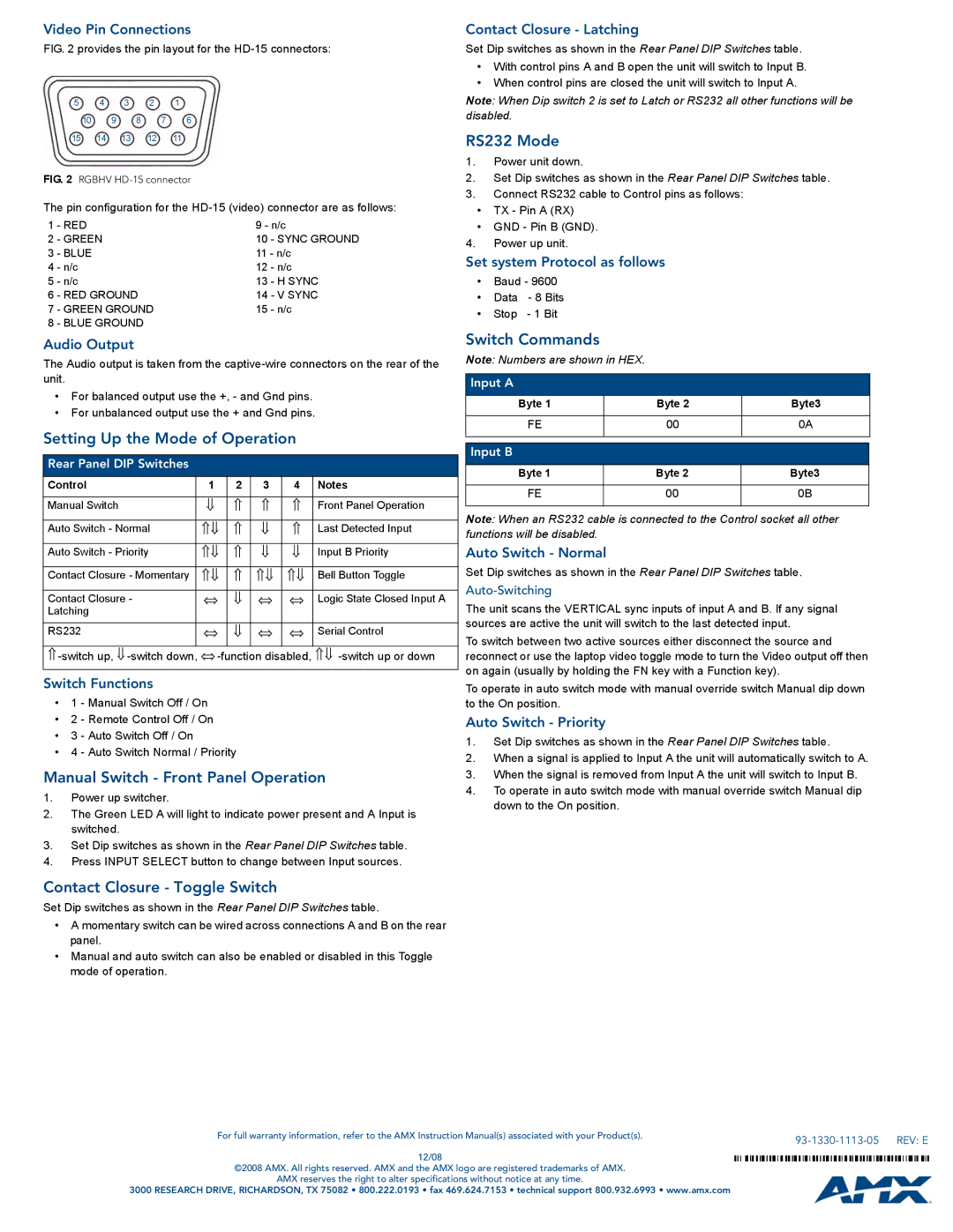
The AMX AVS-SL-0201-824 is a state-of-the-art audio-visual switcher designed for modern media environments. It combines versatility with comprehensive features, making it an ideal choice for various applications, including conference rooms, educational institutions, and event spaces.One of the standout features of the AVS-SL-0201-824 is its ability to handle multiple input sources seamlessly. With support for HDMI, VGA, and various other formats, this switcher ensures compatibility with a wide range of devices, from laptops to media players. The flexibility in input options allows users to easily connect multiple devices and switch between them with minimal effort, ensuring a smooth operational workflow.
The AVS-SL-0201-824 incorporates advanced video processing technologies that enhance the viewing experience. With built-in upscaling capabilities, this device ensures that lower-resolution sources can be displayed in higher quality, providing crystal-clear visuals even when using legacy equipment. Additionally, it supports various resolutions, including 4K, making it suitable for both standard and high-definition applications.
Audio performance is equally impressive with the AMX AVS-SL-0201-824. The switcher features robust audio switching capabilities, enabling users to route audio from multiple sources effortlessly. This is particularly valuable in environments where sound quality is paramount, such as auditoriums or presentation spaces. Moreover, the device supports embedded audio, ensuring that audio and video sources remain synchronized for a seamless experience.
A user-friendly interface enhances the overall functionality of the AVS-SL-0201-824. Featuring a simple touch screen control panel, users can easily navigate through inputs and settings without extensive training. This ease of use is vital in environments where quick adjustments may be necessary, such as in live events or classroom settings where time is of the essence.
The AMX AVS-SL-0201-824 also includes extensive networking capabilities, enabling remote management and monitoring. This connectivity allows users to control the switcher from various locations, making it easier for technicians to manage complex setups. In addition, the device is compliant with industry standards, ensuring it can integrate with existing AV systems seamlessly.
In conclusion, the AMX AVS-SL-0201-824 is an exceptional audio-visual switcher that stands out for its versatility, advanced features, and user-centric design. Whether in a corporate environment, educational facility, or live event setting, this switcher provides the tools needed to create high-quality audio and visual presentations with ease.

