Installation Guide
Overview
Wall Mount panels (NXDs) are contained within a metallic outer housing (back box). This back box is not removed when installing the NXD into a
The
Specifications
Installing a 15" NXD panel within a
The
1.Remove the magnetic faceplate/bezel (A in FIG. 2) from the main NXD unit (B in FIG. 2) by gripping the faceplate and pulling with gentle outward force.
2.Verify the incoming
CB-TP15 (FG032-10) Specifications
Dimensions (HWD) | • 13.48" x 14.18" x 3.49" |
| • 34.24 cm x 36.00 cm x 8.85 cm |
|
|
Included | |
Accessories | • 4 Phillips |
| • 4 Phillips |
|
|
Certifications | • cTUVus Listed |
|
|
WARNING: INSTALLER, LEAVE A GAP BETWEEN THE STUD AND ROUGH- IN BOX TO ACCOMMODATE THE DRYWALL/SHEETROCK.
This gap allows the installation of the drywall/sheetrock after the
Note: The most important thing to remember when mounting this
3.Connect all data and power wiring connectors to their corresponding locations along the side of the
•Verify the terminal end of the power cable is not connected to a power supply before plugging in the
•The USB connectors can be from either a USB extension cable, or
a wireless USB RF transmitter.
Note: Don’t disconnect the connectors from the touch panel. The unit must be installed with the attached connectors before being inserted into the
4.Test the incoming wiring by connecting the panel connections to their terminal locations and applying power. Verify the panel is receiving power and functioning properly to prevent repetition of the installation.
5.Disconnect the terminal end of the power cable from the connected PSN power supply.
6.Carefully slide the main NXD unit (B in FIG. 2) into the
Pre-Wall Installation of the CB-TP15 Rough-In Box
1.Fasten the
2.Remove any necessary wiring knockouts from the
3.Thread the incoming
4.Install the drywall/sheetrock before inserting the main NXD unit into the
7.Insert and secure the four securing
8.Replace the magnet faceplate (A in FIG. 2) back onto the main NXD unit. Make sure to align the Microphone, Light, and PIR Motion sensor locations to their respective openings on the front bezel/faceplate.
9.Connect the terminal
10.Reconnect the terminal power connector on the PSN and apply power
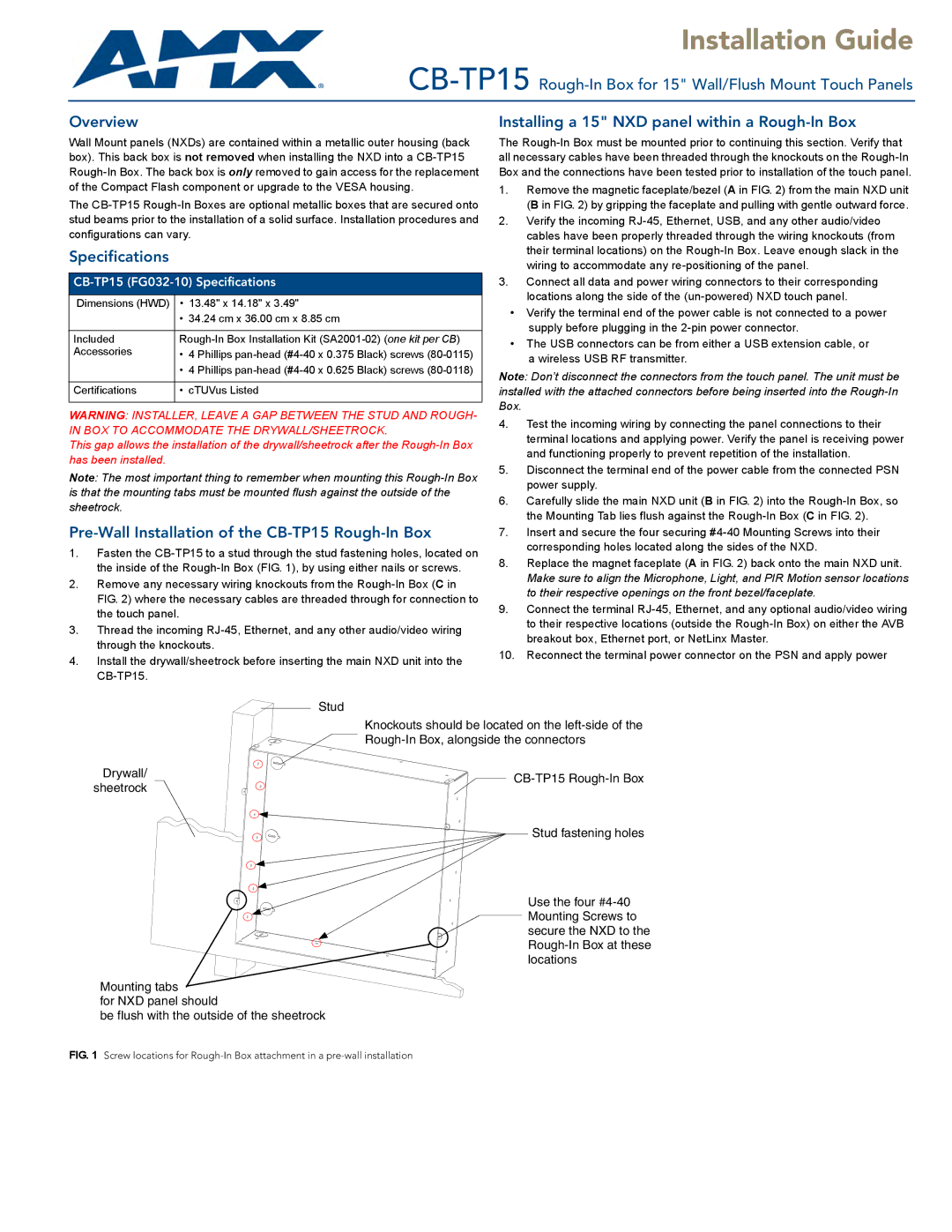
Stud
Drywall/ sheetrock
Knockouts should be located on the
![]()
![]() Stud fastening holes
Stud fastening holes
Use the four
Mounting tabs
for NXD panel should
be flush with the outside of the sheetrock