Installation Guide
NI-900 NetLinx® Integrated Controller
For more detailed installation, configuration, programming, file transfer, and operating instructions, refer to the
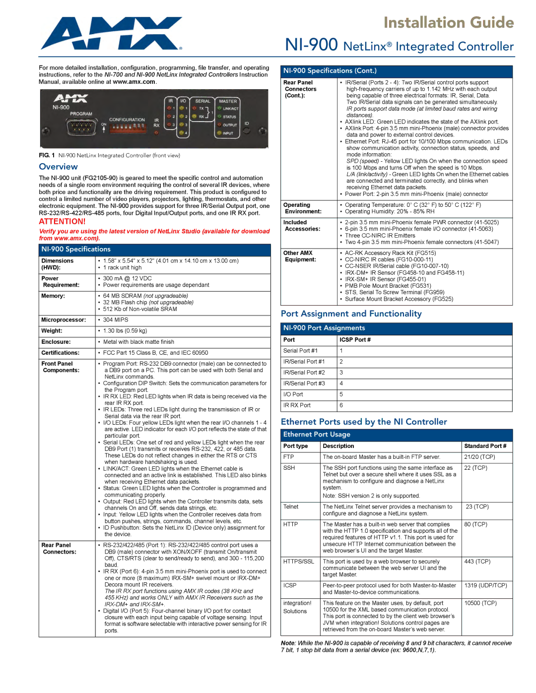
FIG. 1 NI-900 NetLinx Integrated Controller (front view)
Overview
The
ATTENTION!
Verify you are using the latest version of NetLinx Studio (available for download from www.amx.com).
NI-900 Specifications
Dimensions | • | 1.58" x 5.54" x 5.12" (4.01 cm x 14.10 cm x 13.00 cm) |
(HWD): | • | 1 rack unit high |
|
| |
Power | • 300 mA @ 12 VDC | |
Requirement: | • | Power requirements are usage dependant |
|
| |
Memory: | • 64 MB SDRAM (not upgradeable) | |
| • | 32 MB Flash chip (not upgradeable) |
| • | 512 Kb of |
|
| |
Microprocessor: | • 304 MIPS | |
|
|
|
Weight: | • | 1.30 lbs (0.59 kg) |
|
|
|
Enclosure: | • | Metal with black matte finish |
|
| |
Certifications: | • FCC Part 15 Class B, CE, and IEC 60950 | |
|
|
|
Front Panel | • | Program Port: |
Components: |
| a DB9 port on a PC. This port can be used with both Serial and |
|
| NetLinx commands. |
| • | Configuration DIP Switch: Sets the communication parameters for |
|
| the Program port. |
| • | IR RX LED: Red LED lights when IR data is being received via the |
|
| rear IR RX port. |
| • | IR LEDs: Three red LEDs light during the transmission of IR or |
|
| Serial data via the rear IR port. |
| • | I/O LEDs: Four yellow LEDs light when the rear I/O channels 1 - 4 |
|
| are active. LED indicator for each I/O port reflects the state of that |
|
| particular port. |
| • | Serial LEDs: One set of red and yellow LEDs light when the rear |
|
| DB9 Port (1) transmits or receives |
|
| These LEDs do not reflect changes in either the RTS or CTS |
|
| when hardware handshaking is used. |
| • | LINK/ACT: Green LED lights when the Ethernet cable is |
|
| connected and an active link is established. This LED also blinks |
|
| when receiving Ethernet data packets. |
| • | Status: Green LED lights when the Controller is programmed and |
|
| communicating properly. |
| • | Output: Red LED lights when the Controller transmits data, sets |
|
| channels On and Off, sends data strings, etc. |
| • | Input: Yellow LED lights when the Controller receives data from |
|
| button pushes, strings, commands, channel levels, etc. |
| • | ID Pushbutton: Sets the NetLinx ID (Device only) assignment for |
|
| the device. |
|
|
|
Rear Panel | • | |
Connectors: |
| DB9 (male) connector with XON/XOFF (transmit On/transmit |
|
| Off), CTS/RTS (clear to send/ready to send), and 300 - 115,200 |
|
| baud. |
| • | IR RX (Port 6): |
|
| one or more (8 maximum) |
|
| Decora mount IR receivers. |
|
| The IR RX port functions using AMX IR codes (38 KHz and |
|
| 455 KHz) and works ONLY with AMX IR Receivers such as the |
|
|
|
| • | Digital I/O (Port 5): |
|
| closure with each input being capable of voltage sensing. Input |
|
| format is software selectable with interactive power sensing for IR |
|
| ports. |
|
|
|
Rear Panel | • | IR/Serial (Ports 2 - 4): Two IR/Serial control ports support |
Connectors |
| |
(Cont.): |
| being capable of three electrical formats: IR, Serial, Data. |
|
| Two IR/Serial data signals can be generated simultaneously. |
|
| IR ports support data mode (at limited baud rates and wiring |
|
| distances). |
| • | AXlink LED: Green LED indicates the state of the AXlink port. |
| • AXlink Port: | |
|
| data and power to external control devices. |
| • | Ethernet Port: |
|
| show communication activity, connection status, speeds, and |
|
| mode information: |
|
| SPD (speed) - Yellow LED lights On when the connection speed |
|
| is 100 Mbps and turns Off when the speed is 10 Mbps. |
|
| L/A (link/activity) - Green LED lights On when the Ethernet cables |
|
| are connected and terminated correctly, and blinks when |
|
| receiving Ethernet data packets. |
| • | Power Port: |
|
|
|
Operating | • | Operating Temperature: 0° C (32° F) to 50° C (122° F) |
Environment: | • Operating Humidity: 20% - 85% RH | |
|
|
|
Included | • | |
Accessories: | • | |
| • | Three |
| • | Two |
|
| |
Other AMX | • | |
Equipment: | • | |
| • | |
| • | |
| • | |
| • PMB Pole Mount Bracket (FG531) | |
| • | STS, Serial To Screw Terminal (FG959) |
| • | Surface Mount Bracket Accessory (FG525) |
|
|
|
Port Assignment and Functionality
NI-900 Port Assignments
Port | ICSP Port # |
|
|
Serial Port #1 | 1 |
|
|
IR/Serial Port #1 | 2 |
|
|
IR/Serial Port #2 | 3 |
|
|
IR/Serial Port #3 | 4 |
|
|
I/O Port | 5 |
|
|
IR RX Port | 6 |
|
|
Ethernet Ports used by the NI Controller
Ethernet Port Usage
Port type | Description | Standard Port # |
|
|
|
FTP | The | 21/20 (TCP) |
|
|
|
SSH | The SSH port functions using the same interface as | 22 (TCP) |
| Telnet but over a secure shell where it uses SSL as a |
|
| mechanism to configure and diagnose a NetLinx |
|
| system. |
|
| Note: SSH version 2 is only supported. |
|
|
|
|
Telnet | The NetLinx Telnet server provides a mechanism to | 23 (TCP) |
| configure and diagnose a NetLinx system. |
|
|
|
|
HTTP | The Master has a | 80 (TCP) |
| with the HTTP 1.0 specification and supports all of the |
|
| required features of HTTP v1.1. This port is used for |
|
| unsecure HTTP Internet communication between the |
|
| web browser’s UI and the target Master. |
|
|
|
|
HTTPS/SSL | This port is used by a web browser to securely | 443 (TCP) |
| communicate between the web server UI and the |
|
| target Master. |
|
|
|
|
ICSP | 1319 (UDP/TCP) | |
| and |
|
|
|
|
integration! | This feature on the Master uses, by default, port | 10500 (TCP) |
Solutions | 10500 for the XML based communication protocol. |
|
| This port is connected to by the client web browser’s |
|
| JVM when integration! Solutions control pages are |
|
| retrieved from the |
|
|
|
|
Note: While the
7 bit, 1 stop bit data from a serial device (ex: 9600,N,7,1).