With all the same features of the UDM-RX01, the UDM-RX02 adds support for “Common” mode sync, as well as remote power for long cable distance runs.
Compatibility
The UDM-RX02 is compatible for use with the following UDM Hubs:
•UDM-0102 (FG-UDM-0102) - This hub supports Common Synch Mode.
•UDM-0404 (FG-UDM-0404) - This hub supports Common Synch Mode.
•UDM-1604 (FG-UDM-1604C) - This hub supports Common Synch Mode.
•UDM-1604 (FG-UDM-1604) - This hub does not support Common Synch Mode. In this case, the UDM-RX02 will function, but without Common Synch Mode.
Product Specifications
UDM-RX02 Specifications
Power Requirements: | | 24VDC @ .75A |
| | Note: In most cases the UDM-RX02 is remotely powered |
| | by the UDM Multi-Format Distribution Hub (see Powering |
| | |
| | |
Rear Panel Connectors: | |
| |
Power Socket: | | 2.1mm barrel-style DC power socket (female) |
| | |
UDM Hub (RJ45) | | Provides audio/video transport as well as control via Cat5, |
Port: | | Cat5e or Cat6 to an UDM Hub. |
| | |
Serial (RJ12) port: | | Enables an administrator to control the various functions |
| | to the UDM-RX02 from a command line prompt and termi- |
| | nal connection. |
| | • Requires a DB9-to-RJ12 adapter cable (FG-RS01) to |
| | connect to a PC. |
| | • 9600, 8 bit, No Parity, 1 Stop Bit |
| | |
IR Rx Port: | | 3.5mm stereo input port, for connection of an IR receiver |
| | to allow setup of the UDM-RX02, local compensation |
| | controls, and remote control of centrally located IR |
| | devices. |
| | |
IR Tx Port: | | 3.5mm stereo IR Transmitter output port allows one IR- |
| | controlled device (such as a DVD or VCR player) to be |
| | controlled via optional wired IR emitter. |
| | |
Audio Connectors: | | • Black RCA female connector - Digital audio |
| | • White RCA female connector - Analog audio Left |
| | • Red RCA female connector - Analog audio Right |
| | |
Video Connectors: | | • Yellow RCA female connector - CVBS (supports |
| | composite video) |
| | • S-Video - S-video female connector |
| | • VGA - HD15 female connector (supports VGA video) |
| | • Green RCA female connector - Component output: Y |
| | • Blue RCA female connector - Component output: Pb |
| | • Red RCA female connector - Component output: Pr |
| | |
Operating Environment: | | • 35°F - 95°F (5°C - 35°C) |
| | • Max. relative humidity - 85% (non-condensing) |
| | |
Dimensions (HWD): | | 1" x 8 15/16” x 3 3/8” (25 mm x 227 mm x 85 mm) |
| | |
Weight: | | 1.45 lb. (658 g) |
| | |
Certifications: | | • CE |
| | • FCC part 15 Class A |
| | |
Other AMX Equipment: | | • RS232 DB9/RJ12 Connection Cable (FG-RS01) |
| | • UDM-RC02 Multi-Format IR Remote Control |
| | (FG-UDM-RC02) |
| | • IR01 IR Emitter Module (FG-IR01) |
| | • IR03 External IR Receiver Module (FG-IR03) |
| | • UDM-PS 24VDC, 750mA Power Supply (FG-UDM-PS) |
| | |
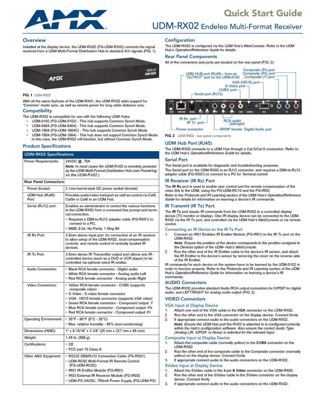
IR Rx port | | | | | | | | |
| | | | | | | |
| | | | | | RCA audio |
IR Tx port | | | | |
| | | | (left/right) |
| | | |
Power connector | | | SPDIF female Digital Audio port |
| |
FIG. 2 UDM-RX02 - rear panel components
UDM Hub Port (RJ45)
The UDM-RX02 connects to a UDM Hub through a Cat 5/Cat 6 connection. Refer to the UDM Hub’s Operation/Reference Guide for details.
Serial Port
The Serial port is available for diagnostic and troubleshooting purposes.
The Serial port on the UDM-RX02 is an RJ12 connector, and requires a DB9-to-RJ12 adapter cable (FG-RS01) to connect to a PC for Terminal control.
IR Receiver (IR Rx) Port
The IR Rx port is used to enable user control and the remote compensation of the video link to the UDM, using the FG-UDM-RC10 and the FG-IR03.
Refer to the Protocols and IR Learning section of the UDM Hub’s Operation/Reference Guide for details for information on learning a device’s IR commands.
IR Transmit (IR Tx) Port
The IR Tx port issues IR commands from the UDM-RX02 to a controlled display device (TV monitor or display). One IR display device can be connected to the UDM- RX02 via the IR Tx port, and controlled via the UDM Hub’s WebConsole or via remote control.
Connecting an IR Device to the IR Tx Port
1.Connect an IR01 Endeleo IR Emitter Module (FG-IR01) to the IR Tx port on the UDM-RX02.
Note: Ensure the position of the device corresponds to the position assigned in the Devices option of the UDM- Hub’s WebConsole.
2.Run the other end of the IR Emitter cable to the device’s IR sensor, and attach the IR Emitter to the device’s sensor by removing the cover on the reverse side of the IR Emitter.
IR commands for each device on the system have to be learned by the UDM-0102 in order to function properly. Refer to the Protocols and IR Learning section of the UDM Hub’s Operation/Reference Guide for information on learning a device’s IR commands.
AUDIO Connectors
The UDM-RX02 provides standard Audio RCA output connectors for S/PDIF for digital audio, and LEFT/RIGHT for analog audio output (FIG. 2).
VIDEO Connectors
VGA Input at Display Device
1.Attach one end of the VGA cable to the VGA connector on the UDM-RX02.
2.Run the other end to the VGA connector on the display device. Connect firmly.
3.If appropriate connect audio to the audio connectors on the UDM-RX02.
Note: Ensure the UDM Hub port the RX02 is attached to is configured correctly within the Hub’s configuration software. Also ensure the correct Audio Type (Analog L/R, S/PDIF, or None) is selected for the relevant input.
Composite Input at Display Device
1.Attach the composite cable (normally yellow) to the CVBS connector on the UDM-RX02.
2.Run the other end of the composite cable to the Composite connector (normally yellow) on the display device. Connect firmly.
3.If appropriate connect audio to the audio connectors on the UDM-RX02.
SVideo Input at Display Device
1.Attach the SVideo cable to the 4-pin S Video connector on the UDM-RX02.
2.Run the other end of the SVideo cable to the SVideo connector on the display device. Connect firmly.
3.If appropriate connect audio to the audio connectors on the UDM-RX02.