Step Motor Selection Guide
| Motor Current | Unipolar | Series Peak | Parallel Peak | Series | Parallel | |
Motor Example | Current | Current | |||||
Number Code | Rating | Rating | Rating | ||||
| Setting | Setting | |||||
|
|
|
|
| |||
|
|
|
|
|
|
| |
23D102S | 02 | 1.0A | 1.0A | 2.0A | 5% | ||
|
|
|
|
|
|
| |
03 | 1.5A | 1.5A | 3.0A | 0% | 20% | ||
|
|
|
|
|
|
| |
04 | 2.0A | 2.0A | 4.0A | 5% | 30% | ||
|
|
|
|
|
|
| |
05 | 2.5A | 2.5A | 5.0A | 10% | 40% | ||
|
|
|
|
|
|
| |
34A106B | 06 | 3.0A | 3.0A | 6.0A | 20% | 50% | |
|
|
|
|
|
|
| |
07 | 3.5A | 3.5A | 7.0A | 25% | 60% | ||
|
|
|
|
|
|
| |
08 | 4.0A | 4.0A | 8.0A | 30% | 70% | ||
|
|
|
|
|
|
| |
09 | 4.5A | 4.5A | 9.0A | 35% | 85% | ||
|
|
|
|
|
|
| |
10 | 5.0A | 5.0A | 10.0A | 40% | 100% | ||
|
|
|
|
|
|
| |
34D311D | 11 | 5.5A | 5.5A | 11.0A | 45% | 100% | |
|
|
|
|
|
|
| |
12 | 6.0A | 6.0A | 12.0A | 50% | 100% | ||
|
|
|
|
|
|
| |
34D213S | 13 | 6.5A | 6.5A | 13.0A | 55% | 100% | |
|
|
|
|
|
|
| |
14 | 7.0A | 7.0A | 14.0A | 60% | 100% | ||
|
|
|
|
|
|
| |
15 | 7.5A | 7.5A | 15.0A | 65% | |||
|
|
|
|
|
|
| |
16 | 8.0A | 8.0A | 16.0A | 70% | |||
|
|
|
|
|
|
| |
42D119D | 19 | 9.5A | 9.5A | 19.0A | 90% | ||
|
|
|
|
|
|
| |
22 | 11.0A | 11.0A | 22.0A | 100% | |||
|
|
|
|
|
|
| |
42D225S | 25 | 12.5A | 12.5A | 25.0A | 100% | ||
|
|
|
|
|
|
|
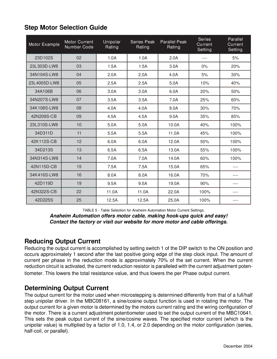
TABLE 5 - Table Selection for Anaheim Automation Motor Current Settings.
Anaheim Automation offers motor cable, making
Reducing Output Current
Reducing the output current is accomplished by setting switch 1 of the DIP switch to the ON position and occurs approximately 1 second after the last positive going edge of the step clock input. The amount of current per phase in the reduction mode is approximately 70% of the set current. When the current reduction circuit is activated, the current reduction resistor is paralleled with the current adjustment poten- tiometer. This lowers the total resistance value, and thus lowers the per Phase output current.
Determining Output Current
The output current for the motor used when microstepping is determined differently from that of a full/half step unipolar driver. In the MBC08161, a sine/cosine output function is used in rotating the motor. The output current for a given motor is determined by the motors current rating and the wiring configuration of the motor. There is a current adjustment potentiometer used to set the output current of the MBC10641. This sets the peak output current of the sine/cosine waves. The specified motor current (which is the unipolar value) is multiplied by a factor of 1.0, 1.4, or 2.0 depending on the motor configuration (series,
December 2004
