8 Lead Motors
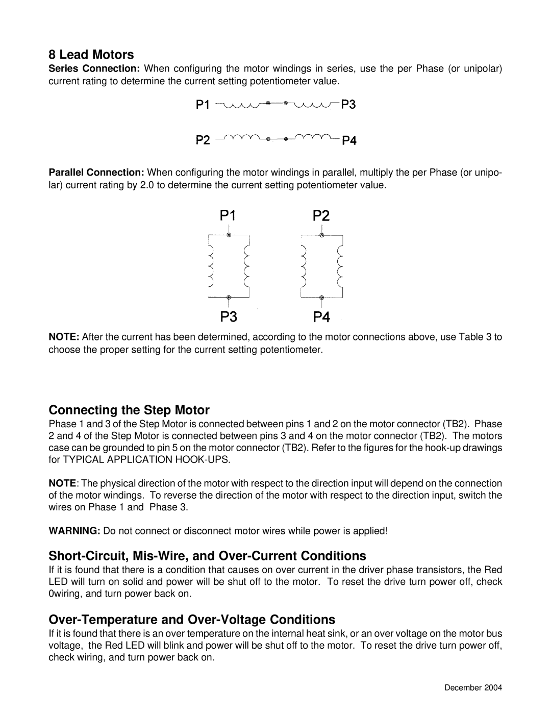
Series Connection: When configuring the motor windings in series, use the per Phase (or unipolar) current rating to determine the current setting potentiometer value.
Parallel Connection: When configuring the motor windings in parallel, multiply the per Phase (or unipo- lar) current rating by 2.0 to determine the current setting potentiometer value.
NOTE: After the current has been determined, according to the motor connections above, use Table 3 to choose the proper setting for the current setting potentiometer.
Connecting the Step Motor
Phase 1 and 3 of the Step Motor is connected between pins 1 and 2 on the motor connector (TB2). Phase 2 and 4 of the Step Motor is connected between pins 3 and 4 on the motor connector (TB2). The motors case can be grounded to pin 5 on the motor connector (TB2). Refer to the figures for the
NOTE: The physical direction of the motor with respect to the direction input will depend on the connection of the motor windings. To reverse the direction of the motor with respect to the direction input, switch the wires on Phase 1 and Phase 3.
WARNING: Do not connect or disconnect motor wires while power is applied!
Short-Circuit, Mis-Wire, and Over-Current Conditions
If it is found that there is a condition that causes on over current in the driver phase transistors, the Red LED will turn on solid and power will be shut off to the motor. To reset the drive turn power off, check 0wiring, and turn power back on.
Over-Temperature and Over-Voltage Conditions
If it is found that there is an over temperature on the internal heat sink, or an over voltage on the motor bus voltage, the Red LED will blink and power will be shut off to the motor. To reset the drive turn power off, check wiring, and turn power back on.
December 2004