DB25 PIN Port Connection Description
1. | No Connection | 14. | Enable All Windings |
2. | No Connection | 15. | No Connection |
3. | No Connection | 16. | No Connection |
4. | No Connection | 17. | No Connection |
5. | No Connection | 18. | No Connection |
6. | No Connection | 19. | A Direction Input |
7. | No Connection | 20. | Z Direction Input |
8 | No Conneciton | 21. | Y Direction Input |
9. | X Direction | 22. | +5VDC Input Required to Power Driver OPTO |
10. | A Step ( Clock Input) | 23. | +5VDC Input Required to Power Driver OPTO |
11. | Z Step ( Clock Input) | 24. | No Connection |
12. | Y Step ( Clock Input) | 25. | No Connection |
13.X Step ( Clock Input)
Optically Isolated Inputs
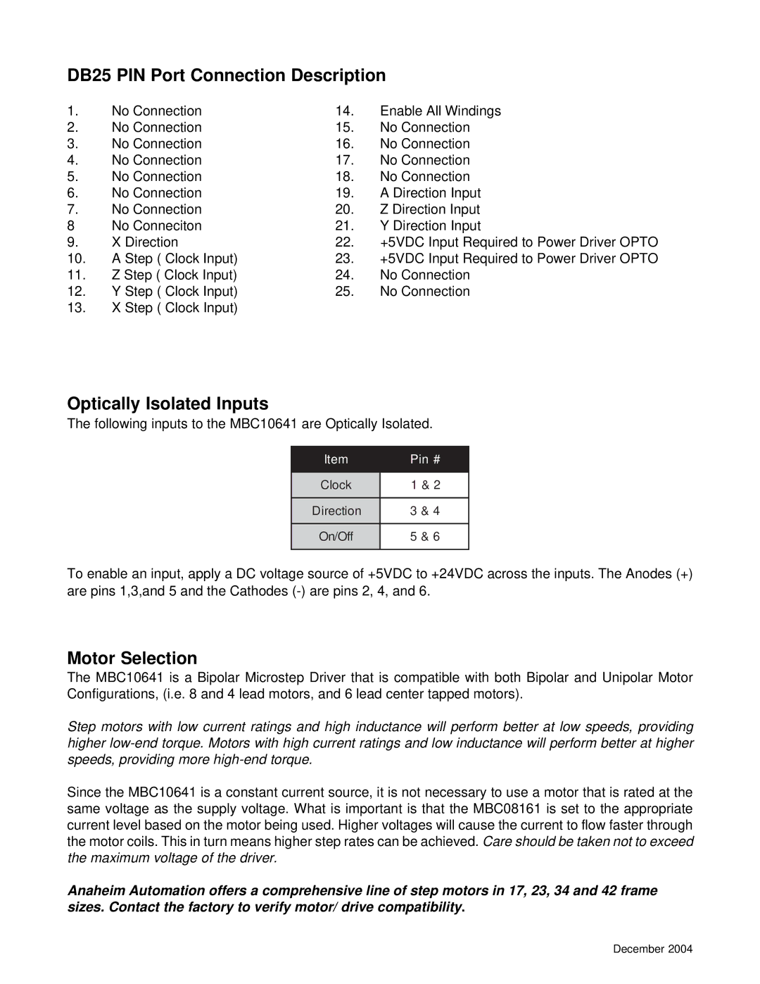
The following inputs to the MBC10641 are Optically Isolated.
Item | Pin # |
|
|
Clock | 1 & 2 |
|
|
Direction | 3 & 4 |
|
|
On/Off | 5 & 6 |
|
|
To enable an input, apply a DC voltage source of +5VDC to +24VDC across the inputs. The Anodes (+) are pins 1,3,and 5 and the Cathodes
Motor Selection
The MBC10641 is a Bipolar Microstep Driver that is compatible with both Bipolar and Unipolar Motor Configurations, (i.e. 8 and 4 lead motors, and 6 lead center tapped motors).
Step motors with low current ratings and high inductance will perform better at low speeds, providing higher
Since the MBC10641 is a constant current source, it is not necessary to use a motor that is rated at the same voltage as the supply voltage. What is important is that the MBC08161 is set to the appropriate current level based on the motor being used. Higher voltages will cause the current to flow faster through the motor coils. This in turn means higher step rates can be achieved. Care should be taken not to exceed the maximum voltage of the driver.
Anaheim Automation offers a comprehensive line of step motors in 17, 23, 34 and 42 frame sizes. Contact the factory to verify motor/ drive compatibility.
December 2004