Evaluation Board User Guide | |
|
|
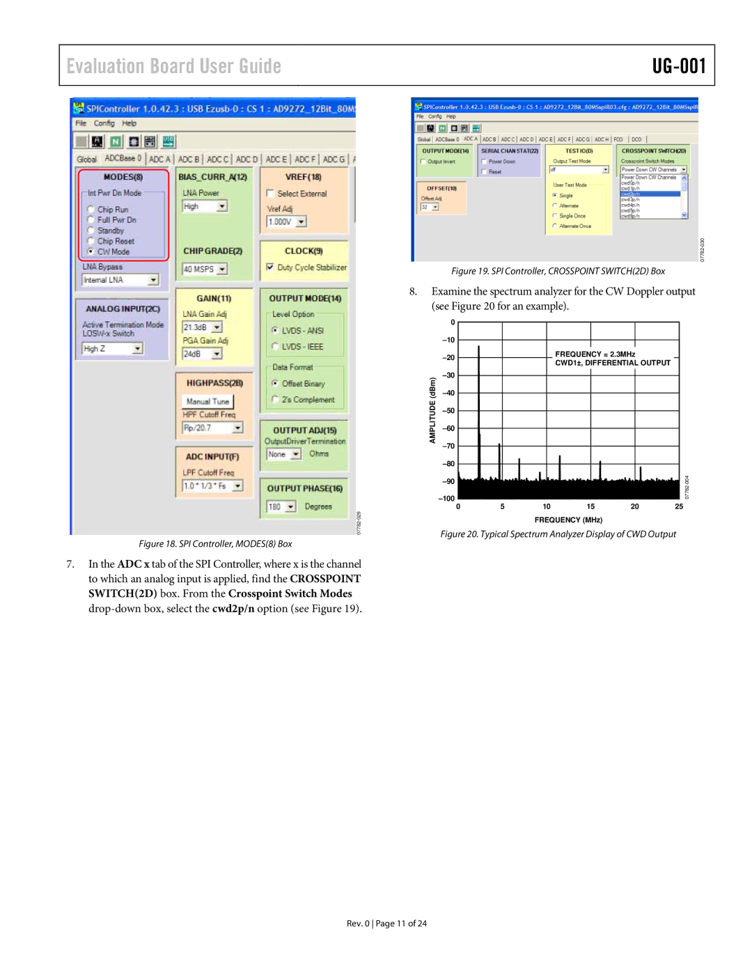
Figure 18. SPI Controller, MODES(8) Box
7.In the ADC x tab of the SPI Controller, where x is the channel to which an analog input is applied, find the CROSSPOINT SWITCH(2D) box. From the Crosspoint Switch Modes
Figure 19. SPI Controller, CROSSPOINT SWITCH(2D) Box
8.Examine the spectrum analyzer for the CW Doppler output (see Figure 20 for an example).
| 0 |
|
|
|
|
|
|
|
|
|
|
| |
|
|
| FREQUENCY = 2.3MHz |
| ||
|
|
| CWD1±, DIFFERENTIAL OUTPUT |
| ||
|
|
|
|
| ||
(dBm) |
|
|
|
|
| |
|
|
|
|
| ||
AMPLITUDE |
|
|
|
|
| |
|
|
|
|
|
| |
|
|
|
|
|
| |
|
|
|
|
|
| |
|
|
|
|
| ||
|
|
|
|
| ||
|
|
|
|
|
| |
| 5 | 10 | 15 | 20 | 25 | |
| 0 | |||||
FREQUENCY (MHz)
Figure 20. Typical Spectrum Analyzer Display of CWD Output
Rev. 0 Page 11 of 24
